


System control processor (CP15) registers
70
NS9750 Hardware Reference
These registers allow you to control which cache-ways of the four-way cache are used
for the allocation on a linefill. When the registers are defined, subsequent linefills
are placed only in the specified target cache way. This gives you some control over
the cache pollution cause by particular applications, and provides a traditional
lockdown operation for locking critical code into the cache.
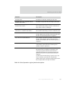
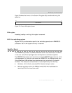
A locking bit for each cache way determines whether the normal cache allocation is
allowed to access that cache way (see Table 30, “Cache Lockdown register L bits,” on
page 71). A maximum of three cache ways of the four-way associative cache can be
locked, ensuring that normal cache line replacement is performed.
Note:
If no cache ways have the L bit set to 0, cache way 3 is used for all
linefills.
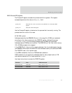
The first four bits of this register determine the L bit for the associated cache way.
The opcode_2 field of the MRC or MCR instruction determines whether the instruction
or data lockdown register is accessed:
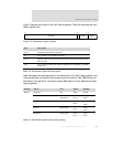
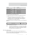
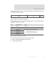
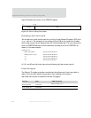
Use the instructions shown in Table 29 to access the CacheLockdown register.
You must modify the Cache Lockdown register using a modify-read-write sequence;
for example:
MRC p15, 0, Rn, c9, c0, 1 ;
ORR Rn, Rn, 0x01 ;
MCR p15, 0, Rn, c9, c0, 1 ;
opcode_2=0 Selects the DCache Lockdown register, or the Unified
Cache Lockdown register if a unified cache is
implemented. The ARM926EJ-S processor has separate
DCache and ICache.
opcode_2=1 Selects the ICache Lockdown register.
Function Data Instruction
Read DCache Lockdown register L bits
MRC p15, 0, Rd, c9, c0, 0
Write DCache Lockdown register L bits
MCR p15, 0, Rd, c9, c0, 0
Read ICache Lockdown register L bits
MRC p15, 0, Rd, c9, c0, 1
Write ICache Lockdown register L bits
MCR p15, 0, Rd, c9, c0, 1
Table 29: Cache Lockdown register instructions