


Pinout and signal descriptions
32
NS9750 Hardware Reference
Notes:
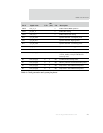
1 Add external pulldown resistor only if the PCI interface is not being used. See the discussion of PCI
bridge configuration in Sample Driver Configurations for information about eliminating the pulldown
resistor.
2 Add external pullup resistors regardless of whether the PCI interface is being used.
3 Add external pullup resistor only if the PCI interface is not being used.
4 Add external pullup resistor in CardBus mode.
5 Add external pulldown resistor in CardBus mode.
6 Add external pullup only if the PCI interface is being used and this signal is also being used.
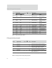
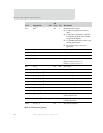
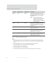
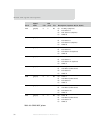
GNT2# CVS1 Output Voltage sense pin. Normally driven low by
NS9750, but toggled during the interrogation of
the external CardBus device to find voltage
requirements.
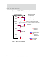
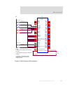
Note: Do not connect directly to the
CardBus connector. See the diagram
"CardBus system connections to
NS9750" on page 462 for a suggested
connection scheme.
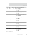
GNT3# CVS2 Output Voltage sense pin. Normally driven low by
NS9750, but toggled during the interrogation of
the external CardBus device to find voltage
requirements.
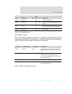
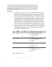
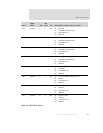
REQ1# CREQ#
4
Input Request from external CardBus device to
NS9750’s internal arbiter.
REQ2# CCD1
4
Input Card detect pin. Pulled up when the socket is
empty and pulled low when the external
CardBus device is in the socket.
REQ3# CCD2
4
Input Card detect pin. Pulled up when the socket is
empty and pulled low when the external
CardBus device is in the socket.
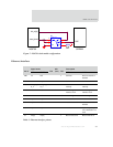
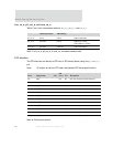
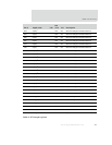
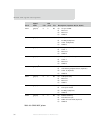
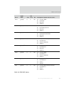
PCI signal CardBus signal CardBus type Description
Table 9: CardBus IO multiplexed signals