System bus arbiter
256
NS9750 Hardware Reference
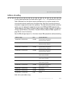
Main arbiter. Contains a 16-entry Bus Request Configuration (BRC) register.
Each BRC entry represents a bus request and grant channel. Each request/
grant channel can be assigned to only one bus master at a time. Each bus
master can be connected to multiple request/grant channels
simultaneously, however, depending on the bus bandwidth requirement of
that master.
Each request/grant channel has a two-bit Bandwidth Reduction Field (BRF)
to determine how often each channel can arbitrate for the system bus —
100%, 75%, 50%, or 25%. A BRF value of 25%, for example, causes a channel
to be skipped every 3 or 4 cycles. The BRC gates the bus requesting signals
going into a 16-entry Bus Request register (BRR). As a default, unassigned
channels in the BRC block the corresponding BRR entries from being set by
any bus request signals. On powerup, only the CPU is assigned to one of the
channels with 100% bandwidth strength as the default setting.
How the bus arbiter works
1 The arbiter evaluates the Bus Request register at every bus clock until one or
more bus requests are registered.
2 The arbiter stops evaluating the Bus Request register until a bus grant is issued
for the previous evaluation cycle.
3 The arbiter grants the bus to requesting channels, in a round-robin manner, at
the rising clock edge of the last address issued for the current transaction (note
that each transaction may have multiple transfers), when a SPLIT response is
sampled by the arbiter, or when the bus is idling.
4 Each master samples the bus grant signal (hgrant_x) at the end of the current
transfer, as indicated by the
hready signal. The bus master takes ownership of the
bus at this time.
5 The arbiter updates the hmaster [3:0] signals at the same time to indicate the
current bus master and to enable the new master’s address and control signals
to the system bus.
See your AMBA standards documentation for detailed information and illustrations of
AMBA AHB transactions.


