www.digiembedded.com
71
Working with the CPU
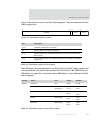
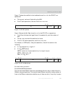
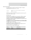
This sequence sets the L bit to 1 for way 0 of the ICache. Figure 20 shows the format
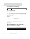
for the Cache Lockdown register.
Figure 20: R9: Cache Lockdown register format
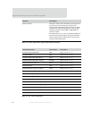
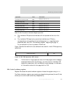
Table 30 shows the format of the Cache Lockdown register L bits. All cache ways are
available for allocation from reset.
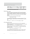
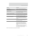
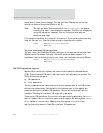
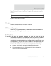
Use one of these procedures to lockdown and unlock cache:
Specific loading of addresses into a cache way
Cache unlock procedure
Bits 4-way associative Notes
[31:16] UNP/SBZ Reserved
[15:4] 0xFFF SBO
[3] L bit for way 3 Bits [3:0] are the L bits for each cache way:
0 Allocation to the cache way is determined by the standard
replacement algorithm (reset state)
1 No allocation is performed to this way
[2] L bit for way 2
[1] L bit for way 1
[0] L bit for way 0
Table 30: Cache Lockdown register L bits
31 03
SBZ/UNP
15 416
SB0
L bits
(cache ways
0 to 3)


