


I2C command interface
546
NS9750 Hardware Reference
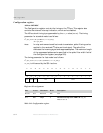
Locked interrupt driven mode
I
2
C operates in a locked interrupt driven mode, which means that each command
issued must wait for an interrupt response before the next command can be issued
(illustrated in "Flow charts," beginning on page 556).
The first bit of the command — 0 or 1 — indicates to which module — master or slave,
respectively — the command in the CMD field (of the
CMD_TX_DATA_REG; see page 548)
is sent. The master module can be sent a master command only; the slave module
can be sent a slave command only (see "Master and slave module commands,"
beginning on page 546, for a list of commands). If a command is sent to the master
module, that module is locked until a command acknowledgement is given. Similarly,
if a command is sent to the slave module, the slave module is locked until it receives
a command acknowledgement. With either module, the acknowledgement can be any
interrupt associated with that module. When a module is locked, another command
must not be sent to that module.
The command lock status can be checked in the
STATUS_RX_DATA_REG.
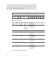
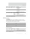
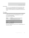
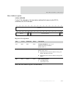
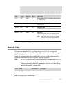
Master module and slave module commands
The I
2
C master recognizes four high-level commands, which are used in the CMD field
of the Command register (see page 548); the I
2
C slave recognizes two high-level
commands:
Command Name Description
00
hex
M_NOP No operation.
04
hex
M_READ Start reading bytes from slave.
05
hex
M_WRITE Start writing bytes to slave.
06
hex
M_STOP Stop this transaction (give up the I
2
C bus).
10
hex
S_NOP No operation. This command is necessary for 16-bit
mode, providing data in TX_DATA_REG without a
command.
16
hex
S_STOP Stop transaction by not acknowledging the byte
received.
Table 335: Master and slave module commands