


www.digiembedded.com
487
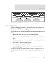
BBus Bridge
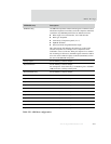
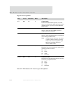
SDRAM config All SDRAM components contain a Mode register, which has control
information required to successfully access the component. The fields
(available in any SDRAM specification) are defined as follows:
Burst length: 4 for 32-bit data bus, 8 for 16-bit data bus
Burst type: Sequential
CAS latency: Component-specific; 2 or 3
OpMode: Standard
Write burst mode: Programmed burst length
This value must be left-shifted by the number of row bits in the
selected components. For example,
4Mx16 components can be
combined to create a 32-bit bus. These parts require 12 row address
bits. Assuming a CAS2 access, the Mode register contents would be
0x22. This value is shifted 12 places to the left (0x00022000) to form
the value in the SDRAM config field.
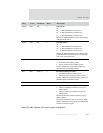
Config register See the Memory Controller chapter.
DynamicRefresh See the Memory Controller chapter.
For example, the value of this entry is
0x00000030 given a 100 MHz
AHB clock and a 7.8125μs refresh period.
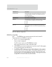
DynamicReadConfig See the Memory Controller chapter.
DynamictRP See the Memory Controller chapter.
DynamictRAS See the Memory Controller chapter.
DynamictSREX See the Memory Controller chapter.
DynamictAPR See the Memory Controller chapter.
DynamictDAL See the Memory Controller chapter.
DynamictWR See the Memory Controller chapter.
DynamictRC See the Memory Controller chapter.
DynamictRFC See the Memory Controller chapter.
DynamictXSR See the Memory Controller chapter.
DynamictRRD See the Memory Controller chapter.
DynamictMRD See the Memory Controller chapter.
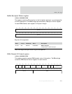
EEPROM entry Description
Table 293: ARM boot configuration