www.digiembedded.com
693
IEEE 1284 Peripheral Controller
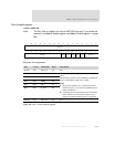
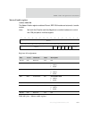
Port Control register
Address: 9040 0108
Note:
The Port Control register can control IEEE 1284 pins only if no modes are
enabled in the Master Enable register (see"Master Enable register" on page
697).
Register bit assignment
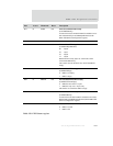
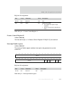
Bits Access Mnemonic Reset Description
D31:08 N/A Reserved N/A N/A
D07 R/W BUSY 0x0 Allows the CPU to directly control the IEEE 1284 pin
values.
The meaning of each bit varies, depending on whether the
mode is compatibility, nibble, byte, or ECP.
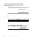
Notes:
Bits [07:03] should be set to 1 before the printer is
enabled (ecr[0]=’1’) to avoid driving IEEE 1284 pins
during initialization.
AutoNegotiate and AutoTransfer must be turned off
before software can take control of these control
signals (see "Master Enable register" on page 697).
D06 R/W N_ACK 0x0
D05 R/W PERR 0x0
D04 R/W SEL 0x0
D03 R/W N_FLT 0x0
D02:00 N/A Reserved N/A N/A
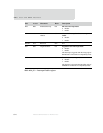
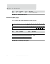
Table 401: pcr — Port Control register
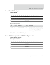
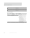
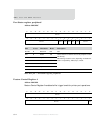
BUSY N_ACK PERR SEL N_FLT
13121110987654321015 14
31 29 28 27 26 25 24 23 22 21 20 19 18 17 1630
Reserved
Reserved Reserved


