DEFINITY Enterprise Communications Server Release 6
Maintenance for R6vs/si
555-230-127
Issue 1
August 1997
Maintenance Object Repair Procedures
Page 10-425DIG-LINE (Digital Line)
10
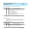
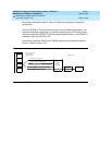
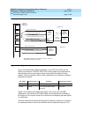
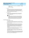
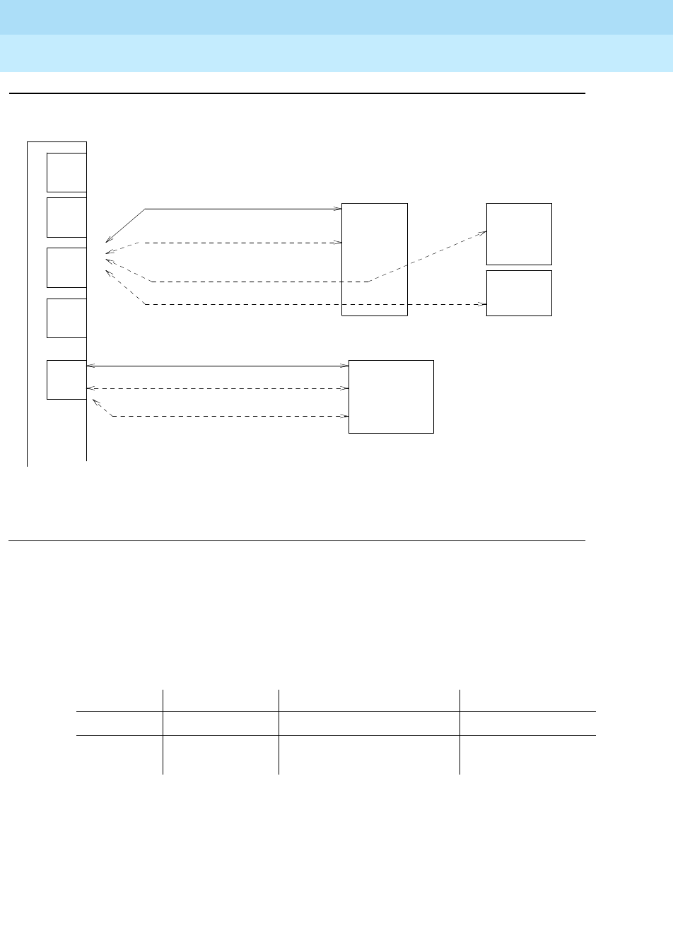
Figure 10-27. Digital Line Connectivity
Only 2-wire Italtel Digital Telephone Models 1 and 2 (IDT1/2) or DAs can be
directly connected to a TN2136. AT&T DCP (4-wire) digital voice terminals and
data modules can be connected to these circuit packs via Italtel’s 2/4-wire
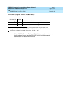
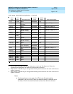
adapter. DAs can operate in either of two modes which are covered by different
maintenance objects:
Digital Line maintenance interacts with Digital Line circuit pack (DIG-BD)
maintenance, and results of DIG-LINE testing can be affected by the health of
the Digital Line circuit pack. Keep this in mind when investigating reported Digital
Line problems.
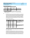
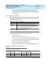
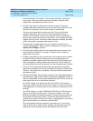
There are instances where the service state of a station is mentioned. It is helpful
to understand what os ment by the different service states that may exist. The
DA Mode Administered as: Endpoint Maintenance Object
Stand-alone PDM Data endpoint only PDMODULE
Linked DTDM IDT1/2 and optional data
terminal
DIG-LINE
TN2136
Digital Line
Circuit Pack
Secondary Information Channel (Data)
Italtel
Digital
Telephone
Model 1/2
Data
Terminal
IDCP
CCITT
V24-V28
Physical Connection
Primary Information Channel (Voice)
Control Channel (Signaling)
Data
Adaptor
(Linked
Mode)
.
.
.
.
. . . . . . . . . . . . . .
Digital Line
.
.
.
.
.
.
.
.
.
.
.
.
.
.
Port
. . . . . . . . . . . . . . . . . . . . . . . . . . . . . . . . . . . . . . . . . . . . . . . . . . . . . . . . . . . . . . . . . . . . . . . . . . . . . . . . . . . . . . . . . . . . . . . . . . . . . . . . . .
.
.
.
.
.
.
.
.
.
.
.
.
.
.
.
.
.
.
.
.
.
.
.
.
.
.
.
.
. . . . . . . . . . . . . . . . . . . . . . . . . . . . . . . . . . . . . . . . . . . . . . . . . . . . . . . . . . . . . . . . . . . . . . . . . . . . . . . . . . . . . . . . . . . . . . . . . . . . . . . . . .
.
.
.
.
.
.
.
.
.
.
.
.
.
.
.
.
.
.
.
.
.
.
.
.
.
.
.
.
.
.
.
.
.
.
.
.
Italtel
Digital
Telephone
Model 1/2
Digital Line
Physical Connection
Primary Information Channel (Voice)
Control Channel (Signaling)
(Secondary Information Channel Unused)
Data Adaptors operating in stand-alone mode are treated as
PDMODULE Maintenance Objects.
. . . . . . . . . . . . . . . . . . . . . . . . . . . . . . . . . . . . . . . . . . . . . . . . . . . . . . . . . . . . . . . . . . . . . . . . . . . . . . . . . . . . . . . . . . . . . . . . . . . . . . . . . . . . . . .
.
.
.
.
.
.
.
.
.
.
.
.
.
.
.
.
.
.
.
.
.
.
.
.
.
.
.
.
.
.
.
.
.
.
.
.
.
.
.
.
.
.
.
. . . . . . . . . . . . . . . . . . . . . . . . . . . . . . . . . . . . . . . . . . . . . . . . . . . . . . . . . . . . . . . . . . . . . . . . . . . . . . . . . . . . . . . . . . . . . . . . . . . . . . . . . . . .
.
.
.
.
.
.
.
.
.
.
.
.
.
.
.
.
.
.
.
.
.
.
.
.
.
.
.
.
.
.
.
.
.
.
.
. . . . . . . . . . . . . .
Port
Port
Port
Port


