


DEFINITY Enterprise Communications Server Release 6
Maintenance for R6vs/si
555-230-127
Issue 1
August 1997
Packet Bus Fault Isolation and Correction
Page 9-13The Maintenance/Test Circuit Pack (TN771D)
9
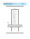
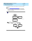
If the system has a TN771 installed in the Port Network to be examined, use the
following steps to enter the standalone mode:
1. Ensure that Alarm Origination is suppressed either at login time or via the
Maintenance-Related System Parameters form.
2. Attach the 258B Six-Port Male Amphenol Adapter to the Amphenol
connector for the TN771’s slot. Connect one end of a D8W 8-wire modular
cable to port 1 of the 258B. Connect the other end of the cable to a 355A
EIA-232 Adapter. Plug the EIA-232 Adapter into the terminal to be used,
and turn the terminal on.
3. Reseat the TN771 circuit pack.
NOTE:
In a High or Critical Reliability system, this causes a Minor, Off-board
alarm to be raised against the Packet Bus. This alarm is not resolved
until the TN771 (in particular, the Packet Bus port is returned to
service. To ensure that Packet Bus alarms have been cleared, it may
be necessary to restore the TN771 to normal mode.
If there is no TN771 in the Port Network, use the following steps to enter the
standalone mode:
1. Attach the 258A Six-Port Male Amphenol Adapter to the Amphenol
connector for the slot into which the TN771 is to be inserted. Connect one
end of a D8W 8-wire modular cable to port 1 of the 258A. Connect the
other end of the cable to a 355A EIA-232 Adapter. Plug the EIA-232
Adapter into the terminal to be used, and turn the terminal on.
2. Insert the TN771 circuit pack into the slot. The system does not recognize
the presence of the circuit pack.
If the standalone mode is entered successfully, the following is displayed on the
connected terminal: