


DEFINITY Enterprise Communications Server Release 6
Maintenance for R6vs/si
555-230-127
Issue 1
August 1997
Maintenance Object Repair Procedures
Page 10-1457UDS1-BD (UDS1 Interface Circuit Pack)
10
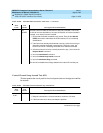
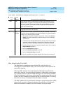
Loss of Signal Alarm Inquiry Test (#138)
This test verifies the synchronization status and continuity of the DS1 link. The
Loss of Signal alarm indicates that the UDS1 Interface circuit pack is unable to
derive the synchronization clock from the DS1 facility. When the UDS1 Interface
circuit pack detects a Loss of Signal alarm, it stops providing the synchronization
clock for the system if it is administered as a timing source and transmits a
Yellow alarm to the remote DS1 endpoint.
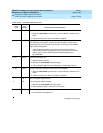
When the Loss of Signal alarm is confirmed, the maintenance software places all
trunks or ports of the UDS1 Interface circuit pack into the out-of-service state.
The inquiry test will run every 10 minutes until the loss of signal has been
restored.
The UDS1 Interface circuit pack raises a Loss of Signal alarm after the signal has
been lost for about 3 seconds. It will not retire the alarm until the signal has
returned for about 10 seconds.
This test is also used to maintain the new AT&T 120A1 CSU Module. This CSU
Module, when combined with the functionality provided by the TN464F circuit
pack, provides functionality equivalent to an external stand-alone AT&T ESF T1
CSU. The combination of the TN464F and 120A1 CSU Module is known as an
Enhanced Integrated CSU (I-CSU).
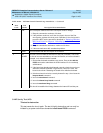
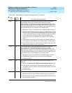
0NO
BOARD
The test could not relate the internal ID to the port (no board). This could
be due to incorrect translations, no board is inserted, an incorrect board is
inserted, or an insane board is inserted.
1. Ensure that the board translations are correct. Execute the add ds1
PCSS command to administer the UDS1 interface if it is not already
administered.
2. If the board was already administered correctly, check the error log to
determine whether the board is hyperactive. If this is the case, the
board is shut down. Reseating the board will re-initialize the board.
3. If the board was found to be correctly inserted in step 1, then issue the
busyout board command.
4. Issue the reset board command.
5. Issue the release busy board command.
6. Issue the test board long command.
This should re-establish the linkage between the internal ID and the port.
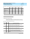
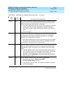
Table 10-493. TEST #135 Internal Loop Around Test — Continued
Error
Code
Test
Result Description/ Recommendation
Continued on next page