


DEFINITY Enterprise Communications Server Release 6
Maintenance for R6vs/si
555-230-127
Issue 1
August 1997
Maintenance Object Repair Procedures
Page 10-246CARR-POW (Carrier Port Power Unit) for AC-Powered Systems
10
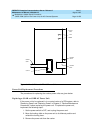
controls in a small cabinet (from a System 75 R1V3 upgrade). Figure 10-14
shows the position of the fuses on the PDU and describes how to replace a fuse.
The TN2036 Voltage Range circuit pack provides easy access for testing the
various voltages on the backplane pins. For more information, refer to the
"Troubleshooting Backplane Voltage Problems" section found in Chapter 5,
"Routine Maintenance Procedures".
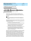
The power unit has two LEDs: if the yellow LED is lit it means the power unit is
operating as normal; if the red LED is lit it means the power unit has a fault; and if
neither is lit it LED means no external power is being supplied. The CARR-POW
(Carrier Port Power Unit) MO represents the pair of power units that power each
carrier in a multicarrier cabinet system. If a problem is reported by hardware for a
power unit on a port carrier, the system can recycle the pair of power units in a
port carrier; however, if the problem is reported on a control carrier, the system
cannot recycle the pair of power units in a control carrier. In a standard
multicarrier cabinet (PPN or EPN) carrier A is the control carrier, and carriers B,
C, D, and E are the port carriers. In a High or Critical Reliability system
multicarrier cabinet (PPN or EPN), carriers A and B are the control carriers, and
carriers C, D, and E are the port carriers. However, carrier B can be recycled
only if the Active Expansion Interface Link and Active Tone-Clock circuit pack are
in the A carrier.
Loss of the 631 DB Carrier Port DC Power Unit in the active control carrier (the A
carrier for a standard system and either the A or B carrier for a High or Critical
Reliability system) causes loss of the administration terminal. In a High or Critical
Reliability system, the Active SPE should switch to the Standby SPE if there is a
CARR-POW alarm.
Recycling a carrier turns off the pair of power units, and turns them back on two
seconds later.
!
WARNING:
Recycling carriers disrupts service for all circuit packs on the carrier.
The DEFINITY Generic 1 can also support neon message waiting lamps on
analog telephones. If this is required, then the carrier(s) that contains the TN769
Analog Neon circuit packs must also be supplied with 165 volt to power the neon
lights. The 165 volt can only be supplied by a TN752 or a TN755B power unit
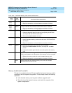
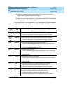
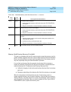
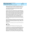
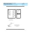
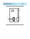
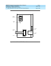
circuit pack. The following table lists all power unit and power-related circuit
packs for the system and indicates the voltages they can supply. Figure 10-12
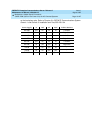
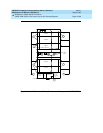
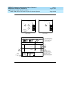
through Figure 10-17 show a schematic of each power unit type. The TN2036
Voltage Range circuit pack provides easy access for testing the various voltages