


DEFINITY Enterprise Communications Server Release 6
Maintenance for R6vs/si
555-230-127
Issue 1
August 1997
Maintenance Architecture
Page 1-4Protocols
1
that contain call-signaling and caller information. These elements conform to
ISDN level-3 protocol. In the case of BRI, the elements are created by the
terminal or data module; for the PRI, the elements are created by the system,
which inserts them into the D-channel at the DS1 port.
For ISDN transmissions, therefore, BRI terminals and data modules, and DS1
ports insert, interpret, and strip both layer-2 DCE information and layer-3
elements. Also, the DS1 port passes layer-3 elements to the system for
processing.
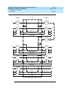
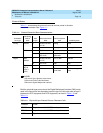
Layers
The Open System Interconnect (OSI) model for data communications contains
seven layers, each with a specific function. Communications to and through the
system concern themselves only with layers 1 and 2 of the model.
Layer 1, or the
physical layer,
covers the physical interface between devices and
the rules by which bits are passed. Among the physical layer protocols are
RS-232, RS-449, X.21, DCP, DS1, and others.
Layer 2, or the
data-link layer
, refers to code created and interpreted by the DCE.
The originating equipment can send blocks of data with the necessary codes for
synchronization, error control, or flow control. With these codes, the destination
equipment checks the physical-link reliability, corrects any transmission errors,
and maintains the link. When a transmission reaches the destination equipment,
it strips any layer-2 information the originating equipment may have inserted. The
destination equipment only passes to the destination DTE equipment the
information sent by the originating DTE equipment. The originating DTE
equipment can also add layer-2 code to be analyzed by the destination DTE
equipment. The DCE equipment treats this layer as data and passes it along to
the destination DTE equipment as it would any other binary bits.
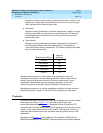
Layers 3 to 7 (and the DTE-created layer 2) are embedded in the transmission
stream and are meaningful only at the destination DTE equipment. Therefore,
they are shown in the figure as ‘‘user-defined,’’ with no state changes until the
transmission stream reaches its destination.