


DEFINITY Enterprise Communications Server Release 6
Maintenance for R6vs/si
555-230-127
Issue 1
August 1997
Maintenance Object Repair Procedures
Page 10-517DS1-BD (DS1 Interface Circuit Pack)
10
Translation Update Test (#146)
The Translation Update Test sends the circuit-pack-level information specified by
System Administration to the DS1 Interface circuit pack. Translation includes the
following data administered for a DS1 Interface circuit pack (see output of
display ds1 PCSS command): DS1 Link Length between two DS1 endpoints,
Synchronization Source Control, All Zero Suppression, Framing Mode, Signaling
Mode, Time Slot Number of 697-Hz Tone, Time Slot Number of 700-Hz Tone, etc.
If a TN767E or later DS1 circuit pack is combined with a 120A CSU Module to
form and Integrated CSU Module, this test will also send the administration for
this Integrated CSU to the circuit pack to assure the board’s translations are
correct. The administration of the CSU Module is done using the DS1 circuit pack
administration form. Translation for the CSU Module includes the following data:
Transmit LBO, Receive ALBO, Supply CPE Loopback Jack Power?, and so forth.
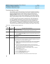
Table 10-173. TEST #146 Translation Update Test
Error
Code Test Result Description/ Recommendation
ABORT Internal system error
1. Retry the command at 1-minute intervals a maximum of 5 times.
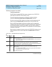
FAIL Internal system software error.
1. Enter the display ds1 PCSS command to verify the DS1 Interface circuit
pack translation.
PASS Translation data has been downloaded to the DS1 Interface circuit pack
successfully.
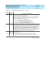
0 NO BOARD The test could not relate the internal ID to the port (no board).
This could be due to incorrect translations, no board is inserted, an incorrect
board is inserted, or an insane board is inserted.
1. Check to ensure that the board translations are correct. Use the add ds1
PCSS command to administer the DS1 interface if it is not already
administered.
2. If board was already administered correctly, check the error log to
determine if the board is hyperactive. If this is the case, the board is shut
down. Reseating the board will re-initialize the board.
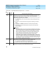
3. If the board was found to be correctly inserted in step 1, issue the
busyout board command.
4. Issue the reset board command.
5. Issue the release busy board command.
6. Issue the test board long command.
This should re-establish the link between the internal ID and the port.
Continued on next page