


DEFINITY Enterprise Communications Server Release 6
Maintenance for R6vs/si
555-230-127
Issue 1
August 1997
Maintenance Object Repair Procedures
Page 10-847MMI-BD
10
Error Log Entries and Test to Clear Values
Notes:
a. The circuit pack stopped functioning or it was physically removed from the
system. The alarm logs approximately 11 minutes after the circuit pack
has been removed and/or the SAKI Sanity Test (#53) fails.
If the circuit pack is in the system and the red LED is on, follow the
instructions for a red alarm in ‘‘
Control and Port Circuit Pack Status LEDs’’
in Chapter 7, ‘‘
LED Interpretation’’. Also, see “Handling Common Port
Circuit Packs.”
b. This circuit pack has been busied out using the busyout board PCSS
command.
c. There are more than four MMI circuit packs in the system. Remove the
circuit pack that generated the error in the error log by locating the slot
indicated by the error.
d. Indicates transient communication problems between the switch and this
circuit pack. Execute the test board PCSS command and refer to the
repair procedures for the Control Channel Looparound Test (#52) in the
XXX-BD section.
1. Run the short test sequence first. If all tests pass, run the long test sequence. Refer to the
appropriate test description and follow the recommended procedures.
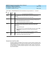
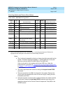
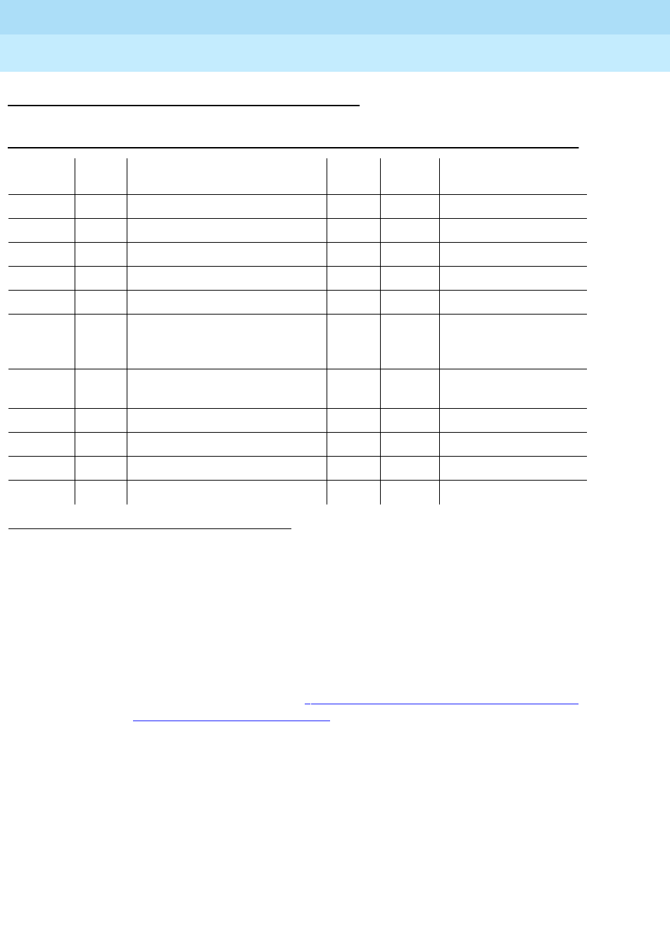
Table 10-282. MMI-BD Error Log Entries
Error
Type
Aux
Data Associated Test
Alarm
Level
On/Of
f Board Test to Clear Value
0
1
0 Any Any Any test board PCSS sh r 1
1 (a) Any None MIN ON
18 (b) 0 Busyout board PCSS WNG OFF release board PCSS
217 (c) 0 None WNG ON
257 (d) 65535 Control Channel Loop Test (#52) MIN ON test board PCSS r 3
513 (e) 4352
to
4357
Uplink error from pack
769 (f) Any MMI Synchronization Status
Test (#1123)
None
1281 (g) Any Circuit Pack Restart Test (#594) MAJ ON
1538 (h) Any Software detected error MIN ON
1793 (i) ANY TSI XTalk (#6) MIN ON test board PCSS l r 3
2049 (j) Any TSI Loop (#1108) MAJ ON test board PCSS l r 3