


DEFINITY Enterprise Communications Server Release 6
Maintenance for R6vs/si
555-230-127
Issue 1
August 1997
Maintenance Object Repair Procedures
Page 10-714ISDN-PLK (ISDN-PRI Signaling Link Port)
10
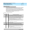
e. “Transmit FIFO Overflow error” This error indicates that the circuit pack is
having problems transmitting data to the Packet Bus, thus affecting the
conveyance of signaling information over the D-channel. Specifically, this
error occurs when the Packet Bus transmit buffers overflow. This condition
probably indicates a hardware problem.
The actual alarming level depends on the options chosen via the set
options command on the G3-MT terminal. ISDN-PRI Signaling Link Port
alarms are treated as Station alarms, and their default alarming option is to
downgrade all alarms to Warning. The value shown in the preceding table
indicates the normal, unfiltered case (option "y" on the
Set Options
form).
f. “Bad DLCI error” This error occurs when a LAPD frame is received across
the DS1 facility which contains a DLCI which does not have a valid entry in
the on-board translation memory. This error normally indicates an
off-board problem usually related to a broken endpoint or a state
mismatch between a remote endpoint and the local call processing
software. Maintenance will not start any testing or generate any alarms in
response to this error.
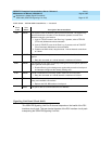
g. “Receive FIFO Overflow error” This error occurs when the circuit pack
detects an overflow of its receive buffers. If it occurs frequently, it may
indicate a LAPD parameter mismatch between the two end-points of a
packet switched connection. LAPD should be able to recover from this
problem, but it may degrade the performance of the Packet Bus.
Maintenance will not start any testing or generate any alarms in response
to this error.
h. This error occurs when the
Signaling Port Packet Bus Loopback Test
(#939)
fails. Run the long test sequence and pay particular attention to the
results of
Test #939
.
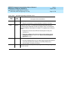
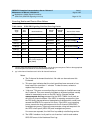
System Technician-Demanded Tests:
Descriptions and Error Codes
Always investigate tests in the order presented in the table below when
inspecting errors in the system. REMINDER: The command line entry to test the
ISDN-PLK MO is: test port PCSSpp (sh or l), where ‘pp’ is ‘24’ for 24-channel
interfaces, and ‘16’ for 32-channel interfaces.
1. D = Destructive; ND = Nondestructive
Order of Investigation
Short Test
Sequence
Long Test
Sequence D/ND
1
Signaling Port Bus Loopback Test (#939) X D
Signaling Link Board Check (#643) X X ND