


DEFINITY Enterprise Communications Server Release 6
Maintenance for R6vs/si
555-230-127
Issue 1
August 1997
Maintenance Object Repair Procedures
Page 10-1434UDS1-BD (UDS1 Interface Circuit Pack)
10
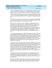
The Packet Interface circuit pack, in turn, communicates with the UDS1 circuit
pack’s D-channel via the Packet Bus. For the INTEL version of D92, the system
software generates and/or receives the actual ISDN-PRI signaling messages
(Q.931). The system software sends and/or receives these ISDN-PRI messages
via the TN765 Processor Interface circuit pack. The Processor Interface circuit
pack, in turn, communicates with the UDS1 circuit pack’s D-channel via the TDM
Bus.
The signaling over the DS1 link must be synchronized between the transmitting
end and the receiving end to ensure error-free communication. Refer to SYNC
(Synchronization) Maintenance documentation for details.
Each trunk, line, and port has its own maintenance strategy. However, each
trunk, line, or port is dependent upon the health of the UDS1 Interface circuit
pack. Refer to the following sections for details: TIE-DS1 documentation for a
DS1 Tie Trunk, CO-DS1 documentation for a DS1 CO Trunk, DID-DS1
documentation for a DS1 DID Trunk, OPS-LINE documentation for a DS1 OPS
Line, WAE-PORT documentation for a Wideband Access Endpoint, ISDN-TRK
documentation for a DS1 ISDN Trunk, PE-BCHL documentation for a PRI
Endpoint Port, and ISDN-LNK documentation for an ISDN-PRI Signaling Link
Port.
The maintenance strategy for the TN464 UDS1 Interface circuit pack (UDS1-BD)
is very similar to the maintenance strategy for the TN767 DS1 Interface circuit
pack (DS1-BD). The same commands are used for administering and testing the
boards. The differences in maintenance strategy between the boards are due to
the UDS1 circuit pack’s direct interface to the Packet Bus which is used for
ISDN-PRI signaling (ISDN-LNK). While both the TN464 and TN767 can support
ISDN-PRI B-channels, ISDN-PRI D-channel signaling applications require a
TN464 UDS1 circuit pack.
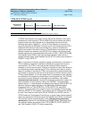
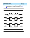
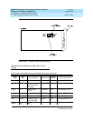
The TN464F (or later suffix) circuit pack combined with AT&T’s new 120A1 CSU
Module forms an Enhanced Integrated CSU. The new 120A1 CSU Module, when
combined with the functionality provided by the TN464F hardware and firmware,
and new switch software, provides functionality equivalent to an external
stand-alone AT&T ESF T1 CSU. The 120A1 CSU Module connects to the TN464F
circuit pack on the I/O connector panel on the back of the port carrier. The new
CSU Module, thus becomes an integrated part of the DEFINITY. system.
Throughout the document, the term 120A1 will mean a 120A1 or later suffix CSU
Module.
The Enhanced Integrated CSU is for use in the United States of America with
1.544 Mbps DS1 service. For further details on the 120A1 CSU Module see
DEFINITY. Communications System Generic 1, Generic 2, and Generic 3 V1 and
V2 - Integrated CSU Module Installation and Operation
, 555-230-193, Issue 1,
December 1993.
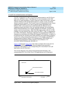
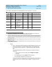
The TN464F and 120A1 CSU Module support on-demand loopback tests that
assist in the detection of faults between the TN464F circuit pack and the CSU
Module, between the Integrated CSU and the optional Customer Premises