


DEFINITY Enterprise Communications Server Release 6
Maintenance for R6vs/si
555-230-127
Issue 1
August 1997
Maintenance Object Repair Procedures
Page 10-1316TDM-BUS (TDM Bus)
10
In a High or Critical Reliability System
A less destructive procedure for processor complex circuit packs can be used
rather than the one described for standard systems. Perform the procedure on
the Processor Interface circuit pack and Network Control circuit pack before it is
attempted for any other processor complex circuit packs.
Pulling out processor complex circuit packs from the Standby SPE does not
require powering down the carrier and does not require starting the system
again. See Chapter 6, ‘‘
Reliability Systems: A Maintenance Aid’’ for more details.
1. Perform Procedure 2 for the suspected processor complex circuit pack in
the Standby SPE to determine if it is causing the TDM Bus problem. The
status system command indicates which SPE is in standby mode. If the
suspected circuit pack is the Tone-Clock circuit pack, make sure it is in
standby mode via the status system command or its LED state. The
SYSTEM CLOCKS and SYSTEM TONES fields of the status system form
should read "standby" or the yellow LED on the circuit pack is off.
NOTE:
When doing Procedure 2 as a request of Procedure 3, pull out
processor circuit packs instead of purple slot port circuit packs.
2. If it fails to identify the processor complex circuit pack as the cause of the
problem, perform an SPE switch via the reset system i command (see
Note).
NOTE:
Make sure that the current Standby SPE is in the standby mode via
the status system command before performing the SPE switch.
3. Perform Procedure 2 for the suspected processor complex circuit pack in
the new Standby SPE to determine if it is causing the TDM Bus problem.
4. If it fails again to identify the processor complex circuit pack as the cause
of the problem, perform Procedure 2 for the remaining processor complex
circuit packs.
5. If this procedure fails to identify the cause of the problem, go to Procedure
4.
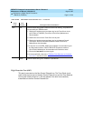
Procedure 4
Procedure 4 attempts to isolate the failure to a particular set of carriers, and then
checks only the circuit packs in those carriers. This procedure involves
terminating the TDM Bus so that certain carriers are disconnected from the TDM
Bus. This is done by moving the TDM Bus terminators (AHF1) on the carrier
backplane. To terminate a TDM Bus at the end of a particular carrier, the TDM
Bus cable that connects the carrier to the next carrier should be unplugged and
replaced with the TDM Bus terminator. The TDM Bus terminators can be taken
from one carrier to the other. To get to the TDM Bus cables, remove the back