


DEFINITY Enterprise Communications Server Release 6
Maintenance for R6vs/si
555-230-127
Issue 1
August 1997
Maintenance Object Repair Procedures
Page 10-1443UDS1-BD (UDS1 Interface Circuit Pack)
10
If the UDS1 board detects only one of these hardware problems, then the
error will disappear when none of these faults are detected for 10 minutes.
If the same Aux Data value is logged more than once in a 24 hour period,
the circuit pack should be replaced.
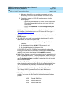
g. LAN External RAM Error. This error occurs when there is a hardware fault
in the PPE external RAM. The RAM is used for message buffering to and
from the Packet Bus. This error should not occur regularly. If this error is
seen quite frequently (10 times within 30 minutes), the circuit pack should
be replaced.
h. Transmit FIFO Underflow Error. This error occurs when the circuit pack
cannot find the "end of frame" bit when transmitting a frame to Packet Bus.
An alarm will be raised if this error occurs three times within 10 minutes.
Clear the alarm via the following commands: busyout board PCSS, reset
board PCSS, test board PCSS long, release board PCSS. If the error
recurs within 10 minutes, then replace the circuit pack.
i. Unable to Write LAN Translation RAM Error. This error occurs when a call
is aborted because there are no available translation RAM locations for
the call connection attempt. An alarm will be raised if this error occurs two
times within 10 minutes. Clear the alarm via the following commands:
busyout board PCSS, reset board PCSS, test board PCSS long,
release board PCSS. If the error recurs within 10 minutes, then replace
the circuit pack.
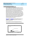
j. CSU Module missing. The
Near-End CSU Type
field on the
add ds1
form
has been administered as
integrated
but the 120A1 CSU Module is not
physically connected (or is improperly connected) to the TN464F board
on the back of the port carrier.
If using the 120A1 CSU Module, plug (or replug) the CSU Module into the
TN464F circuit pack’s connector on the I/O connector panel on back of
the carrier. Otherwise, change the
Near-End CSU Type
field using the
change ds1
form to
other
.
If this error remains after plugging the CSU Module into the board’s
connector, there could be a problem with the I/O connector panel.
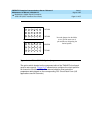
k. CSU Module not expected. The 120A1 CSU Module is physically
connected to the TN464F board on the back of the port carrier but the
Near-End CSU Type
field on the
add ds1
form has not been administered
as
integrated
.
If the 120A1 CSU Module is to be used, use the
change ds1
command to
change the
Near-End CSU Type
field to
integrated
. Otherwise, physically
remove the 120A1 CSU Module from the back of the port carrier.
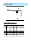
l. DS1 configuration error. Attempting to use the 120A1 CSU Module with a
TN464F circuit pack that is configured for 32-channel (2.048 Mbps)
operation. The CSU Module only works with a DS1 board configured for
24-channel (1.544 Mbps) operation in the United States of America.