


DEFINITY Enterprise Communications Server Release 6
Maintenance for R6vs/si
555-230-127
Issue 1
August 1997
Maintenance Object Repair Procedures
Page 10-1187STRAT-3 (Stratum 3 Clock)]
10
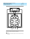
The output of the CI and PAI cards go directly to the TN780 Tone-Clock circuit
pack via two 25-pair amp-terminated cables. All of the cards have red and/or
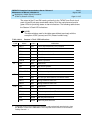
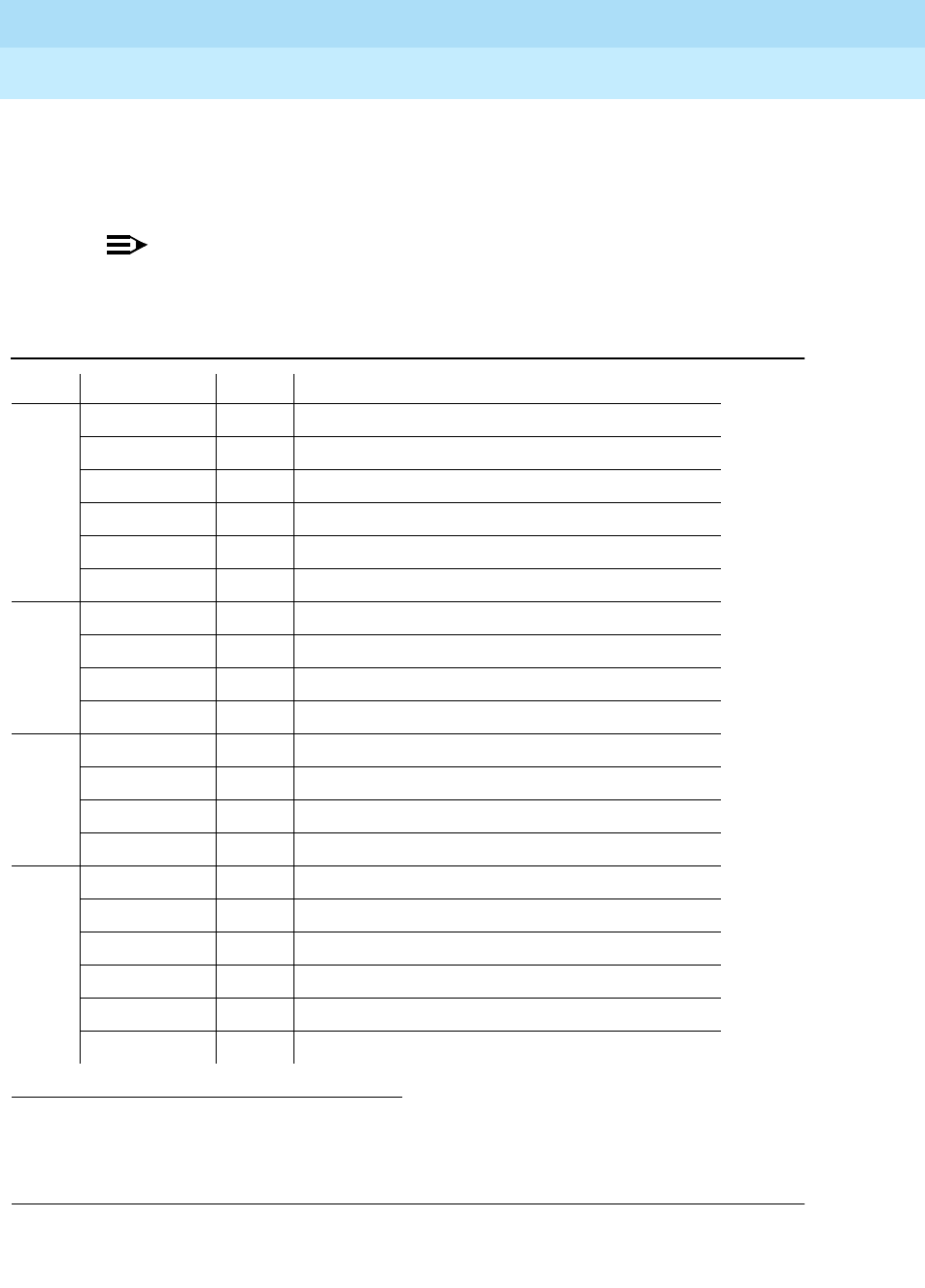
green LEDs for providing status or alarm indications. The following table shows
the Stratum 3 Clock LED indications.
NOTE:
The abbreviations used in the table were defined previously with the
exception of SRC (source) and PLL (Phase Locked Loop).
1. Composite Clock source refers to the protocol used to electrically transfer timing from
the Stratum 3 clock to the PBX switch. The Composite Clock source is not relevant to
Definity Generic 1.1.
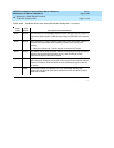
Table 10-411. Stratum 3 Clock LED Indications
Card Name Color Indication
PAI REF A Red Loss of input reference A or CI A failed
REF B Red Loss of input reference B or CI A failed
ST A Red Failed Stratum 3 clock A
ST B Red Failed Stratum 3 clock B
PWR A Green -48VDC A present
PWR B Green -48VDC B present
CI FAIL Red Card failure
DS1 Green DS1 source present
CC Green Composite clock source
1
present
SRC ACTIVE Green Card is currently on-line
ST3 FAIL Red Card failure
LOCK Red PLL lost sync with reference or holdover mode
REF A Red Timing Reference from CI A
REF B Red Timing Reference from CI B
TOC FAIL Red Card failure
PORT ALM Red Output port alarm (one or more)
ST Green Reference present from ST clock
INPUT Green Reference present from CI
500’ Green 500 feet phase advance
1000’ Green 1000 feet phase advance