


DEFINITY Enterprise Communications Server Release 6
Maintenance for R6vs/si
555-230-127
Issue 1
August 1997
Maintenance Architecture
Page 1-9Protocols
1
Connectivity Rules
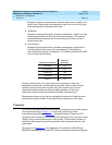
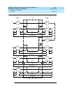
Figure 1-1 implies the following connectivity rules:
■ Only the DS1 port and the analog trunk port are trunking facilities (all other
ports are line ports). For communication over these facilities, the
destination DCE equipment can be a hemisphere away from the system,
and the signal can traverse any number of intervening switching systems
before reaching the destination equipment.
■ Data originating at any type of digital device, whether DCP or BRI, can exit
the system at any type of digital port — BRI, digital-line, PRI, DS1, and
others; as long as the call destination is equipped with a data module
using the same DMI mode used at the call origin. This is because once the
data enters the system through a digital port, its representation is uniform
(raw bits at layer 1, and DMI at level 2), regardless of where it originated.
■ Although data entering the system through an EIA port has not been
processed through a data module, the port itself has a built-in data
module. Inside the system, port data is identical to digital line data. Data
entering the system at a DCP line port can exit at an EIA port. Conversely,
data entering the system at an EIA port can exit at any DCP line port. The
destination data module must be set for Mode-2 DMI communication.
■ Voice-grade data can be carried over a DS1 facility as long as the
destination equipment is a modem compatible with the originating modem
■ If a mismatch exists between the types of signals used by the endpoints in
a connection (for example, the equipment at one end is an analog
modem, and the equipment at the other end is a digital data module), a
modem-pool member must be inserted in the circuit. When the endpoints
are on different switches, it is recommended that the modem-pool
member be put on the origination or destination system. A modem-pool
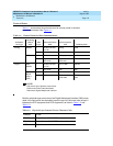
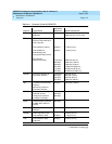
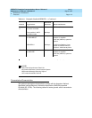
Table 1-3. Digital Multiplexed Interface (DMI) Mode Versus
Character Code
DMI Mode Code
0 Synchronous (64 kbps)
1 Synchronous (56 kbps)
2 Asynchronous 8-bit ASCII (up to 19.2 kbps), and
synchronous
3 Asynchronous 8-bit ASCII, and private proprietary