DEFINITY Enterprise Communications Server Release 6
Maintenance for R6vs/si
555-230-127
Issue 1
August 1997
LED Interpretation
Page 7-6Control and Port Circuit Pack Status LEDs
7
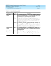
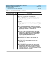
■ Check the Error Log for TONE-BD and TDM-BUS errors. Enter test
tdm P where P is the port network containing the relevant slot.
Refer to” Restarting Nonfunctioning Port Circuit Packs” in Chapter
10, ‘‘Maintenance Object Repair Procedures’’ in the general
description of the “TDM-BUS”. Enter test tone-clock PC, where P
is the network containing the relevant slot, and C is the carrier
containing the relevant slot. Follow appropriate sections for any
“TONE-BD” and “TDM-BUS” errors.
■ Reseat the suspect circuit pack.
!
WARNING:
Reseating some circuit packs may be very destructive (for example,
Control Carrier circuit packs.)
Wait 5 minutes. Then issue the list configuration board PCSS
command. If the result indicates that the system still has not
registered the circuit pack, go to next step.
■ Try to insert the circuit pack into a different slot and try to insert a
different circuit pack into the suspect slot (provided the
maintenance documentation for this circuit pack does not warn
against either of these actions).
■ If the system seems to be functioning correctly, but the circuit pack
does not start communicating with the system, replace the circuit
pack.
2. Green (test)
—the system is running tests on this circuit pack.
3. Yellow (busy)
—indicates that the circuit pack is in use.
NOTE:
A port circuit pack also lights its red LED when it performs
initialization tests (for example, when the circuit pack is initially
inserted into the system). If all initialization tests pass, the red LED is
turned off. If any initialization tests fail, the red LED remains lighted
and the circuit pack is not placed into service.
Packet circuit packs such as the TN556 ISDN BRI-Line and TN570
Expansion Interface perform extensive initialization tests and light both the
red and green LEDs during that testing.
During the various states of operation (start-up testing, normal operation,
circuit failure, and so forth) circuit pack status LED indications appear as
shown in Table 7-1
.


