


DEFINITY Enterprise Communications Server Release 6
Maintenance for R6vs/si
555-230-127
Issue 1
August 1997
Maintenance Object Repair Procedures
Page 10-1173STBY-SPE (Standby SPE)
10
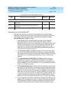
1030 ABORT The component on which the test was to be run is on the Standby SPE. This
test may only be run on this component when it resides on the Active SPE. If it
is absolutely necessary to conduct this test on the Standby SPE component,
implement the following steps to make it become an Active SPE component.
1. Issue the refresh spe-standby command to return the Standby SPE to
Standby Mode. This command may have to be issued multiple times. If the
refresh spe-standby command successfully completes five times without
the Standby SPE becoming labeled "standby" on the status system form,
wait 20 minutes. This does not include cases where the command
completes with the terminal message line errors "Refresh not successful;
use ‘display errors’ to check for STBY-SPE errors" or "Cannot interrupt
Standby SPE while entering maintenance mode; please try later." Issue the
refresh spe-standby command once more.
2. Issue the reset system interchange command in order to cause an SPE
switch. At this point, the component resides on the Active SPE.
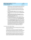
1030
(cont’d.)
ABORT 3. Move the SPE Select switches to make the SPE with the problem the
current Active SPE. This action prevents software from switching to the
other SPE since the current SPE has the error against it.
4. Repeat the test.
5. If the test passes and the alarm is resolved, return the SPE Select switches
to the AUTO position.
6. If the test fails and the defective circuit pack is identified, the circuit pack
needs to be replaced. However, the circuit pack now resides on the
current Active SPE. Return the SPE Select switches to the AUTO position.
Issue the refresh spe-standby command and then execute a reset
system interchange command to cause an SPE switch.
7. The system is now on the healthy SPE. Replace the defective circuit pack
on the Standby SPE as previously identified in Step 4. Refer to the
"Replacing Defective SPE Circuit Packs" section in Chapter 6, ‘‘
Reliability
Systems: A Maintenance Aid’’.
8. Repeat the procedure, beginning with Step 1.
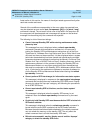
2011
2012
2013
ABORT Internal system error
1. Retry the command at 1-minute intervals a maximum of 5 times.
2015 ABORT The Standby SPE Maintenance/Tape Processor did not reply to an Active SPE
request to hold the Standby SPE Processor reset. The communication path
between the Active SPE and the Standby SPE Maintenance/Tape Processor
may have failed, or the Standby SPE Maintenance/Tape Processor may have
failed. Follow the procedures described for Error Code 2024 in the STBY-SPE
section.
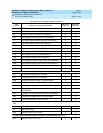
Table 10-410. Test Result Error Codes Associated with the Standby SPE — Continued
Error
Code
Test
Result Description/ Recommendation
Continued on next page