DEFINITY Enterprise Communications Server Release 6
Maintenance for R6vs/si
555-230-127
Issue 1
August 1997
Maintenance Object Repair Procedures
Page 10-1177STBY-SPE (Standby SPE)
10
2024
(cont’d.)
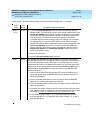
ABORT 10. Issue the display errors command and check to see if Error Type 58 is
logged against STBY-SPE. If an Error Type 58 is logged OR if none of the
three error types are logged, the problem is either the Standby SPE
Processor circuit pack or the Standby SPE Memory circuit pack or the
carrier A Duplication Interface circuit pack.
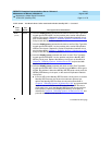
■ If the red LED on the Standby SPE Processor circuit pack is on and the
Standby SPE Processor circuit pack has not been replaced yet,
replace the Standby SPE Processor circuit pack as described in
Chapter 6, ‘‘
Reliability Systems: A Maintenance Aid’’ and proceed with
Steps 11, 12, and 13. If the red LED on the Standby SPE Processor
circuit pack is on, and if the Standby SPE Processor circuit pack has
been replaced, replace the Standby SPE Memory circuit pack as
described in Chapter 6, ‘‘
Reliability Systems: A Maintenance Aid’’ and
proceed with Steps 11, 12, and 13.
■ If the red LED on the Standby SPE Memory circuit pack is on, replace
the Standby SPE Memory circuit pack as described in Chapter 6,
‘‘Reliability Systems: A Maintenance Aid’’ and proceed with Steps 11,
12, and 13.
■ If the red LED on the carrier A Duplication Interface circuit pack is on,
replace the carrier A Duplication Interface circuit pack as described in
Chapter 6, ‘‘
Reliability Systems: A Maintenance Aid’’ and proceed with
Steps 11, 12, and 13.
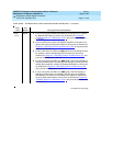
■ If none of the three red LEDs is on AND if this is the first attempt to clear
the problem, replace the Standby SPE Processor circuit pack as
described in Chapter 6, ‘‘
Reliability Systems: A Maintenance Aid’’ and
proceed with Steps 11, 12, and 13.
2024
(cont’d.)
ABORT ■ If none of the three red LEDs is on AND if this is the second attempt to
clear the problem, replace the Standby SPE Memory circuit pack as
described in Chapter 6, ‘‘
Reliability Systems: A Maintenance Aid’’ and
proceed with Steps 11, 12, and 13.
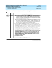
■ If none of the three red LEDs is on AND if this is the third attempt to
clear the problem, replace the carrier A Duplication Interface circuit
pack as described in Chapter 6, ‘‘
Reliability Systems: A Maintenance
Aid’’ and proceed with Steps 11, 12, and 13.
■ If none of the three red LEDs is on AND if this is the fourth attempt to
clear the problem, replace the carrier B Duplication Interface circuit
pack as described in Chapter 6, ‘‘
Reliability Systems: A Maintenance
Aid’’ and proceed with Steps 11, 12, and 13.
■ If none of the three LEDs is on AND if this is the fifth attempt to clear the
problem, escalate the problem.
Table 10-410. Test Result Error Codes Associated with the Standby SPE — Continued
Error
Code
Test
Result Description/ Recommendation
Continued on next page


