DEFINITY Enterprise Communications Server Release 6
Maintenance for R6vs/si
555-230-127
Issue 1
August 1997
Routine Maintenance Procedures
Page 5-73Install DS1 CPE Loopback Jack (T1 Only)
5
9. Repeat Steps 5 through 8 as desired to observe bit error rate
characteristics. Also, wait 1 to 10 minutes between Steps 5 through 7. One
minute without errors translates to better than a 1 in 10 to the eighth error
rate. Ten minutes without errors translates to better than a 1 in 10 to the
ninth error rate.
10. If the test runs for 1 minute with an error count of 0, confirm that the 3-in-24
pattern error detector is operating properly by entering test ds1-loop
<location> inject-single-bit-error. This causes the 3-in-24 pattern
generator on the DS1 circuit pack to inject a single-bit error into the
transmit pattern. A subsequent list meas ds1 summary <location>
command displays the bit error count. If a count greater than 1 is
displayed, replace the ICSU and retest. If the problem continues, replace
the DS1 circuit pack.
11. Terminate the test by entering test ds1-loop <location> end
cpe-loopback-jack-test. Wait about 30 seconds for the DS1 to re-frame
on the incoming signal and clear DS1 facility alarms.
Loopback termination fails under the following conditions:
a. The span is still looped somewhere. This could be at the loopback
jack, at the ICSU, or somewhere in the network. This state is
indicated by a fail code of 1313. If the red LED on the loopback
jack is on, replace the ICSU. Re-run the test and verify that the
loopback test terminates properly. If not, replace the DS1 circuit
pack and repeat the test.
b. The DS1 cannot frame on the incoming span’s signal after the
loopback jack is powered down. This means that there is
something wrong with the receive signal into the loopback jack
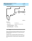
from the “dumb” block or the Smart Jack. If the service provider
successfully looped and tested the span, up to the Smart Jack, this
condition isolates the problem to the wiring between the loopback
jack and the Smart Jack. Refer to “Loopback Jack Fault Isolation
Procedures” for information on how to proceed in this case. The
test cannot be successfully terminated until a good signal is
received. To properly terminate the test before a good receive
signal is available, enter reset board <location>.
12. Restore the “TX LBO” field to the original value recorded in Step 2.
13. Release the DS1 circuit pack using the release board UUCCSSpp
command.
14. Leave the loopback jack connected to the DS1 span.


