


DEFINITY Enterprise Communications Server Release 6
Maintenance for R6vs/si
555-230-127
Issue 1
August 1997
Maintenance Object Repair Procedures
Page 10-603EXP-INTF (Expansion Interface Circuit Pack)
10
2. Check for errors via the display errors command with the Category field
set to "tone" and the Active alarms field set to "n." Some of the alarms on
EPN objects might have been resolved if the EPN went down. Refer to the
appropriate MO Maintenance documentation for descriptions of any of the
errors occurring at about the same time as the EXP-LINK errors. Resolve
any active alarms. Also, if Error Type 18 was logged against the SYNC MO
when the EPN went down, the problem was probably that the
synchronization on-line reference became invalid. Since reference
switching was disabled, the Tone-Clock did not switch from the invalid
reference. Therefore, the Tone-Clock circuit pack put out a system clock
that was "out of spec." Issue the enable synchronization-switch
command. If the EPN is down, reseat the Tone-Clock circuit packs on the
EPN. This action should restore the EPN to service.
Execute Steps 3 and 4 in the order most convenient to you and least
destructive to the customer.
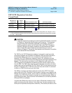
3. Check if the fiber optic cable is transmitting properly via the following
procedure on one of the out-of-service links:
a. Carefully record the symptoms (yellow LED pattern and tests
failing) that were occurring on the PPN Expansion Interface circuit
pack and the EPN Expansion Interface circuit pack. Clearly
indicate which symptoms are occurring on which Expansion
Interface circuit pack.
!
WARNING:
Before proceeding, note which is the current transmit fiber and
which is the current receive fiber for proper reconnection.
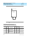
b. Disconnect the transmit and receive fiber pair from the lightwave
transceiver on the back of the PPN Expansion Interface circuit pack
slot (see Figure 10-30 on page 10-657).
c. Connect what was formerly the transmit fiber to the receive jack.
d. Connect what was formerly the receive fiber to the transmit jack.
e. Perform Steps b, c, and d on the opposite end of the fiber and the
lightwave transceiver on the back of the EPN Expansion Interface
circuit pack slot.
NOTE:
If it is more convenient for you, execute Steps b, c, and d on
the EPN Expansion Interface circuit pack first.
f. If the symptoms which were formerly occurring on the PPN
Expansion Interface circuit pack are now occurring on the EPN
Expansion Interface circuit pack and vice versa, the fiber is
defective and should be replaced.