


DEFINITY Enterprise Communications Server Release 6
Maintenance for R6vs/si
555-230-127
Issue 1
August 1997
Routine Maintenance Procedures
Page 5-32Software Upgrade
5
Set the basic control cabinet power supply circuit breaker to OFF.
Replace Circuit Packs
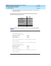
1. Remove the combined TN786B/CPP1 Processor/Memory circuit pack
from the basic control cabinet.
2. Install the TN790 Processor circuit pack into the control cabinet slot
labeled “PROCR.”
Reboot the System
1. Set the basic control cabinet power supply circuit breaker to ON.
2. The system performs the reset level 4 rebooting process by loading
translations from the translation card. This takes 10 to 15 minutes.
3. Peel the paper backing from the new circuit pack position label
(designation strip) and affix it to the front of the basic control cabinet.
4. Install a circuit pack blank into the slot previously occupied by the CPP1.
Power Down Duplicated Control Cabinet
!
CAUTION:
Do not power down the entire system. This defeats the purpose of high or
critical reliability configurations.
Set the duplicated control cabinet power supply circuit breaker to OFF.
Replace Circuit Packs
1. Remove the combined TN786B/CPP1 Processor/Memory circuit pack
from the duplicated control cabinet.
2. Install the TN790 Processor circuit pack into the control cabinet slot
labeled “PROCR.”
Reseat DEFINITY LAN Gateway System
Reseat the LAN Gateway assembly into its backplane connectors in the carrier.
Reseat DEFINITY AUDIX System
Reseat the AUDIX assembly into its backplane connectors.
Reboot the System
1. Set the duplicated control cabinet power supply circuit breaker to ON.