


DEFINITY Enterprise Communications Server Release 6
Maintenance for R6vs/si
555-230-127
Issue 1
August 1997
Maintenance Object Repair Procedures
Page 10-1213SYNC (Synchronization)
10
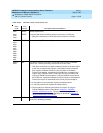
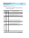
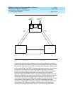
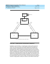
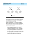
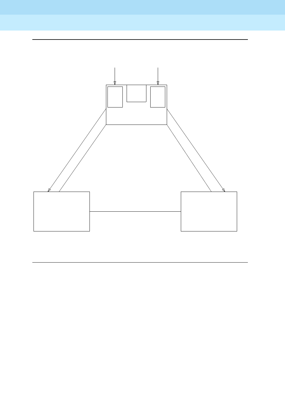
Figure 10-87. Typical Stratum 4 Synchronization Configuration
If the primary synchronization reference in the previous diagram is providing a
valid timing signal, then the flow of system synchronization would travel from the
DS1 interface circuit pack in the PPN across the active Expansion Interface fiber
link to the two EPNs. The PPNDS1 interface circuit pack provides a timing signal
for the PPN Tone-Clock circuit pack and the PPN Tone-Clock circuit pack
provides timing for all circuit packs in the PPN. The PPN Expansion Interface
circuit pack uses the timing generated by the Tone-Clock circuit pack to
generate a data stream which is sent across the Expansion Interface link to the
Expansion Interface circuit packs in the two EPNs. The EPN Expansion Interface
circuit pack uses the received data stream to generate a timing signal. The
Tone-Clock circuit pack in the EPNs uses this signal to generate timing for all the
circuit packs in their respective EPNs. The PPN, in the above mentioned
scenario, is designated the
master
port network and the EPNs are called
slave
port networks. The
master
port network is defined as the port network that
contains the system synchronization source. If the primary synchronization
PPN
EPN
EPN
TONE/
CLOCK
DS-1
INTF
DS-1
INTF
PRIMARY
REFERENCE
SECONDARY
REFERENCE
TIMING
INFO
EXPANSION INTERFACE (EI) LINK*
* EPN-TO-EPN LINKS ARE NOT USED TO CARRY TIMING
TIMING
INFO
EI LINK EI LINK