DEFINITY Enterprise Communications Server Release 6
Maintenance for R6vs/si
555-230-127
Issue 1
August 1997
Maintenance Object Repair Procedures
Page 10-1149STBY-SPE (Standby SPE)
10
two) in the Active SPE, the same number of PI circuit packs must be
present in the Standby SPE. If one SPE has a Packet Control Circuit Pack,
the other SPE must also have one. If the set of circuit packs in each SPE is
not identical, alarms could result against the STBY-SPE, DUPINT,
SHDW-CIR, PI-BD, PKT-CTRL, PROCR, MEM-BD and MEMORY
maintenance objects.
The accessing and testing of the Standby SPE may be affected by the health of
the circuit packs through which the Active SPE communicates with the Standby
SPE. These circuit packs include the Active SPE Processor circuit pack, the
Duplication Interface circuit pack in the A carrier, and the Standby SPE
Processor circuit pack. Additionally, the Inter-Carrier Cable (ICC) and the
backplane affect the ability of the Active SPE to communicate with the Standby
SPE. The ability to shadow Active SPE memory into Standby SPE memory is
affected by the Duplication Interface circuit pack in the A carrier, the Duplication
Interface circuit pack in the B carrier, and the Memory circuit pack(s) in the
Standby SPE. Additionally, the Active SPE Memory Bus, the ICC, backplane, and
the Standby SPE Memory Bus affect the ability to correctly shadow Active SPE
memory into Standby SPE memory.
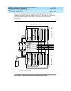
These dependencies can be seen in Figure 10-84
for the TN790. These figures
depict the interconnection between the two SPEs of a high or critical reliability
system. The following abbreviations are used in the figures:
■ DUPINT for Duplication Interface circuit pack
■ PROCR/MEM for TN786B or TN790 Processor Circuit Packs with Memory
■ PROCR for Processor Circuit Pack
■ MEMORY for Memory Circuit Pack(s)
■ MTP for Maintenance Processor in Processor Circuit Pack
■ NETCON for Network Control Circuit Pack
■ MEM CARD for Memory Card Plugged in the Network Control Circuit Pack
■ PI for Processor Interface Circuit Pack(s)
■ PKT CTRL for Packet Control Circuit Pack
■ TN CLK for Tone-Clock Circuit Pack
■ TDM BUS for Time Division Multiplex Bus
■ PACKET BUS for Packet Bus
■ M-BUS for Memory Bus
■ ICC for Inter-Carrier Cable
■ SCC for Single-Carrier Cabinet
The dashed lines in the figure represent important logical connections between
components.


