


DEFINITY Enterprise Communications Server Release 6
Maintenance for R6vs/si
555-230-127
Issue 1
August 1997
Maintenance Object Repair Procedures
Page 10-553DUPINT (Duplication Interface Circuit Pack)
10
DUPINT (Duplication Interface Circuit
Pack)
In a High or Critical Reliability PPN system, there are two Duplication Interface
circuit packs: one in carrier A and one in carrier B. Together, Duplication
Interface circuit pack A and Duplication Interface circuit pack B provide memory
shadowing (see “SHDW-CIR” for a full description) and communication between
software on the Active and Standby SPEs. By itself, Duplication Interface circuit
pack A provides control of the duplicated Processor circuit pack, environmental
maintenance monitoring and control, and administration terminal connection.
Duplication Interface circuit pack A controls a lead that lets the Tone-Clock
circuit packs know which of them is supposed to be active and additional leads
that control which SPE is active. The system software can request that either the
SPE Select lead or Tone-Clock lead be changed.
Duplication Interface circuit pack A controls and monitors the same environment
leads that the Maintenance/Tape Processor does in a PPN a system without High
or Critical Reliability. Duplication Interface circuit pack A also supports the serial
channel to the PPN administration terminal in a high or critical reliability PPN. The
administration terminal connects to Duplication Interface circuit pack A via a
connector on the back of carrier A labeled DOT. At any time, the administration
terminal may be disconnected from Duplication Interface circuit pack A and
connected directly to the active Maintenance/Tape Processor by attaching the
administration terminal to the connector marked TERM on the active carrier. This
connection should only be made if the administration terminal fails to function
since a problem with the Duplication Interface circuit pack A may be present.
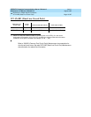
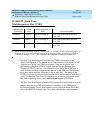
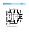
The Duplication Interface circuit packs communicate over the Inter-Carrier Cable
(ICC). The ICC connects the Duplication Interface circuit packs via pin fields on
the backplane. The ICC consists of two 25-pin connector cables known as ICC-A
and ICC-B. (Note: A single-carrier cabinet system has an ICC-C also.) The pin
fields where ICC-A and ICC-B connect are clearly labeled on the backplane near
the pin fields for the Duplication Interface circuit packs. The ICC carries several
important leads related to maintaining a high or critical reliability system.
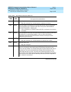
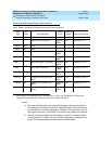
1. Alarms on Duplication Interface circuit pack in the A carrier are always major alarms and alarms
on Duplication Interface circuit pack in the B carrier are always warning alarms. Determine the
carrier to test via the PORT field from the Alarm or Error Log.
MO Name (in
Alarm Log)
Alarm
Level Initial Command to Run
1
Full Name of MO
DUPINT MAJOR test duplication 1C Duplication Interface Circuit Pack
DUPINT WARNING test duplication 1C Duplication Interface Circuit Pack