DEFINITY Enterprise Communications Server Release 6
Maintenance for R6vs/si
555-230-127
Issue 1
August 1997
Routine Maintenance Procedures
Page 5-49System Features
5
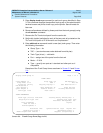
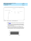
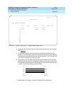
Screen 5-4. Trunk Group Form — E & M Mode (Page 2 of 2)
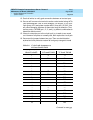
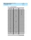
10. Locate the Tie Trunk port terminal connections at the cross-connect field.
See Table 5-4
.
11. At the cross-connect field, disconnect outside trunk facilities from the Tie
Trunk ports and mark the disconnected wires for later reconnecting the
Tie Trunk ports back to normal operation. The D Impact Tool (AT-8762) is
required to perform this step.
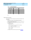
12. Use jumper wires (DT 24M-Y/BL/R/G and DT 24P-W/BRN) and the D
Impact Tool to connect wiring between the two ports assigned in Step 9 at
the cross-connect field. For example, if the two ports on the Analog Tie
Trunk circuit pack are port 1 and 2, connect the wirings as shown below:
Page 2 of 5
TRUNK GROUP
GROUP MEMBER ASSIGNMENTS
Port Name Mode Type Answer Delay
1: B1901 E & M t1 stan
2: B1902 E & M t1 comp
3:
4:
5:
6:
7:
8:
9:
10:
11:
12:
13:
14:
15:
E&M E&M
comp t1 stan t1
E2
M1
M2
E1
R2
R11
T2
T11
R12
R1
T12
T1
2 Port 1 Port


