DEFINITY Enterprise Communications Server Release 6
Maintenance for R6vs/si
555-230-127
Issue 1
August 1997
Maintenance Object Repair Procedures
Page 10-211CABINET (Cabinet Sensors)
10
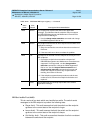
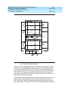
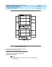
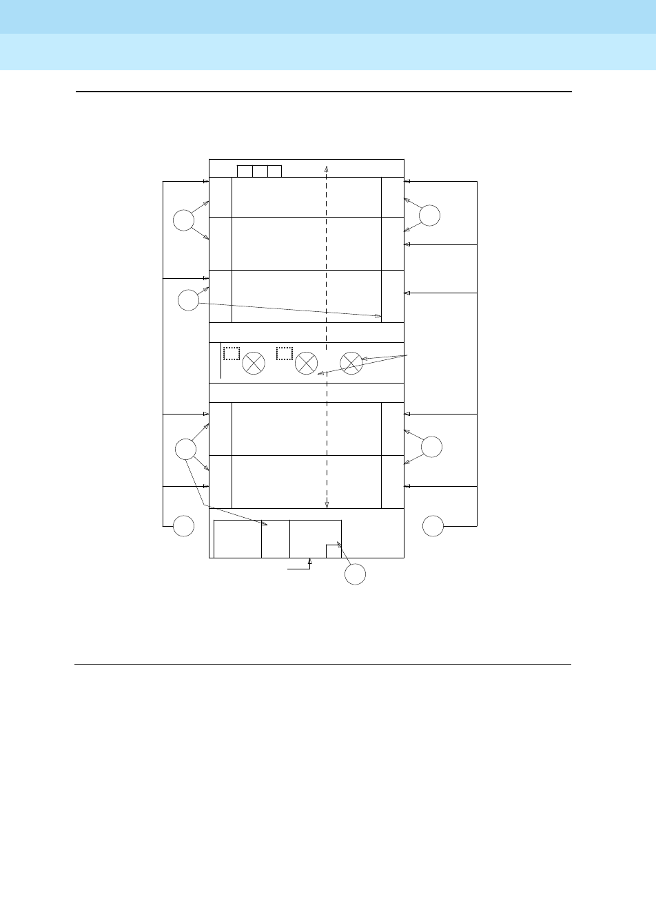
Figure 10-10. Multicarrier Cabinet Environment Components (CABINET)
[Non-Variable Speed Fan Option]
Sensor S1 informs the Maintenance/Tape Processor, the Duplication Interface
circuit pack, or the EPN Maintenance circuit pack when the temperature at the
top of the cabinet reaches 65
0
C (149
0
F). Sensor S2 is not monitored by any
circuit pack. However, when the temperature at the top of the cabinet reaches
70
0
C (158
0
F), this sensor causes the Power Distribution Unit to shut down
power to the entire cabinet. At this point, Emergency Transfer is invoked, and no
other system functions are provided.
The S3 and S4 sensors constantly report the temperature at the air exhaust in the
cabinet (top and bottom S3 sensors) and at the air intake (S4 sensors). The
AHD1 circuit pack uses this information to determine fan speed and air flow
alarm state. If there is at least a 15
0
C (27
0
F) air temperature difference between
631
DA
CARRIER A
FILTER
A
H
631
DA
631
DB
631
DB
CARRIER B
F
L
O
W
S4
FILTER
AC
AC
AC
A
FANS -3 FRONT
3 BACK
F1
D
S4
1
S2 S3 S1
631
DA
AC
F3
CARRIER C 631
A
I
R
DB
AC
F2
631
DA
631
DA
631
DB
631
DB
F4
CARRIER D
CARRIER E
I
R
F
L
O
W
DC
FUSE F1-F7
F5
F6 F7
DC
BATTERY
CHARGER
BATTERY &
AC
DIST.
RING
S3
GENERATOR
ON BACK OF
PDU, FUSE
F9 ON FRONT
OF PDU
F9
POWER DISTRIBUTION UNIT


