


DEFINITY Enterprise Communications Server Release 6
Maintenance for R6vs/si
555-230-127
Issue 1
August 1997
Reliability Systems: A Maintenance Aid
Page 6-21Repair Procedures for High and Critical Reliability
6
cause a PEI. If the refresh or system interchange are unsuccessful, then
use the SPE select switches to hard select the Standby SPE (this will result
in a COLD 2 restart of the system).
4. If the upgrade software (reset system interchange) command is
successful, an SPE-interchange results in the new Active SPE performing
a COLD 2 (HOT) restart. Follow the “Circuit Pack Replacement Procedure”
described later. If the upgrade software command failed, determine why
the failure occurred, resolve the problem, and repeat this entire
procedure.
Handling DUPINT Alarms in the Active SPE
Check for the existence of DUPINT alarms against the Active SPE Duplication
Interface circuit pack. If there are Active SPE DUPINT alarms, inform the
customer that a reboot of the system may be required and determine a time at
which a reboot may be done. At that time, complete the following steps:
1. Make sure that the translation card in the Active SPE has the most current
translations. If it does not, issue save translations spe-active to put the
most current translations on it.
2. Exchange the translation cards in the Active SPE and Standby SPE so that
the Standby SPE contains the card with the most current translations.
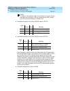
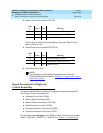
3. Throw the SPE Select Switches on the TN772 Duplication Interface circuit
packs to force an SPE-interchange so that the current Standby SPE
becomes the new Active SPE. If SPE B is currently the Standby SPE, throw
both SPE Select Switches to the right. If SPE A is currently the Standby
SPE, throw both SPE Select Switches to the left.
If the Duplication Interface circuit pack actually severed the Memory
Shadowing Link resulting in corruption of Standby SPE Memory, the
SPE-interchange results in the new Active SPE performing a Reboot.
However, if the defect in the Duplication Interface circuit pack did not
sever the Memory Shadowing Link, the SPE-interchange results in the new
Active SPE performing a Warm Start instead.
4. After the SPE-interchange is complete, log into the terminal. Follow the
“Circuit Pack Replacement Procedure” described later for each circuit
pack to be replaced in the new Standby SPE.
Upgrading SPE Circuit Packs
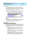
Determine which SPE is the Standby SPE by issuing the status system
command. Look at the SPE and MODE fields in the upper left corner of the form.
The Active SPE; it is labeled as “active.” The other SPE is the Standby SPE and is
labeled as either “standby,” “maint,” or “down.”
Follow the ‘‘
Circuit Pack Replacement Procedure’’ described later
for each
Standby SPE circuit pack to be upgraded
.