DEFINITY Enterprise Communications Server Release 6
Maintenance for R6vs/si
555-230-127
Issue 1
August 1997
Maintenance Object Repair Procedures
Page 10-600EXP-INTF (Expansion Interface Circuit Pack)
10
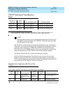
■ TDM BUS The Time Division Multiplex Bus that connects circuit packs
within a cabinet
■ EXP-INTF The Expansion Interface (EXP-INTF) circuit pack
■ FIBER The optical fiber used to connect Expansion Interface circuit packs
■ MAINT EPN Maintenance (MAINT) circuit pack
■ PKT-BUS The Packet Bus used to carry ISDN-BRI signalling information
■ MGR 1 The local administration terminal
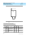
To determine which Expansion Interface Link is active and which is standby for
each Expansion Interface pair, the status system command can be used.
Alternately, visual inspection shows that the Active Expansion Interface circuit
packs have the yellow LED on solid or blink a pattern two seconds on, 200
milliseconds off. The Standby Expansion Interface circuit packs have the yellow
LEDs off.
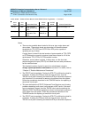
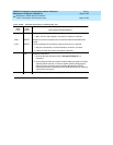
Notes:
a. This flashing code corresponds to error codes 769 and 770 from the
Hardware Error Log and indicates a failure of Test #238. These error
codes are usually accompanied by error code 1281 (no Expansion
Interface detected on opposite end of fiber). This condition may be
caused by the absence of the opposite end Expansion Interface circuit
pack, a broken or missing fiber, or a missing lightwave transceiver on
either Expansion Interface circuit pack.
b. This flashing code corresponds to error code 1281 from the Hardware
Error Log and indicates a failure of Test #237. This condition is usually due
to a failed Expansion Interface circuit pack on the opposite end of the
fiber.
c. This is the normal state for an EPN Active Expansion Interface circuit pack
that is also the bus master in the EPN.
d. This is the normal state for an Active Expansion Interface circuit pack that
is not the bus master. It is also the state of the TN776 Expansion Interface
circuit pack immediately after circuit pack initialization when the system
has not yet assigned a role to it (that is, Active or Standby). To distinguish
between these two situations, use the status system command. If the link
Condition LED on LED off
Fiber Out-of-Frame (a) 0.1 second 0.1 second
In frame, No Neighbor (b) 0.5 second 0.5 second
Expansion Interface Active (c) 2 second 0.2 second
Expansion Interface Active (d) solid on never off
Expansion Interface Standby (e) never on solid off


