


DEFINITY Enterprise Communications Server Release 6
Maintenance for R6vs/si
555-230-127
Issue 1
August 1997
Routine Maintenance Procedures
Page 5-82Install DS1 CPE Loopback Jack (T1 Only)
5
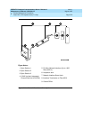
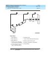
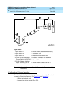
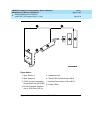
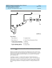
Configurations Using Fiber Multiplexers
Use the loopback jack when customer premises DS1 wiring connects to an
on-site fiber multiplexer (MUX) and allows wiring to the network interface point on
the MUX to be remotely tested. This requires that ICSUs be used on DS1 wiring
to the MUX.
Fiber MUXes can take the place of Interface termination feeds as shown in Figure
5-11 , Figure 5-12, Figure 5-13, and Figure 5-14. Test these spans using the
same procedures as metallic spans. Note the following points:
1. Fiber MUXes may have loopback capabilities that can be activated by the
service provider from the CO end. These may loop the signal back to the
CO or back to the DS1 board. If the MUX provides the equivalent of a line
loopback on the “problem” DS1 facility, this may be activated following a
successful loopback jack test and used to isolate problems to the wiring
between the loopback jack and the MUX.
2. Be aware that there are installations that use repeatered metallic lines
between the MUX and the “dumb” block. Theses lines require DC power
for the repeaters and this DC power is present at the “dumb” block
interface to the CPE equipment.
A loopback jack is required in this
configuration to properly isolate and terminate the DC power
.
To check for the presence of DC, make the following 4 measurements at the
network interface jack:
1. From Transmit Tip (T, Pin 5) to Receive Tip (T1, Pin 2)
2. From Transmit Ring (R, Pin 4) to Receive Ring (R1, Pin 4)
3. From Transmit Tip (T, Pin 5) to Transmit Ring (R, Pin 4)
4. From Receive Tip (T1, Pin 2) to Receive Ring (R1, Pin 4)
All measurements should read 0 (zero) volts DC. For pin numbers and pin
designations, refer to
Integrated Channel Service Unit (ICSU) Installation and
Operation
, 555-230-193.
Operating Charasteristics
If a TN464F or TN767E and a 120A2 were installed in a system running pre-G3V3
software and the software is later upgraded to G3V3 Release 3 or later, reseat
the DS1 circuit pack so that the ICSU administration fields will appear on the DS1
administration form.