DEFINITY Enterprise Communications Server Release 5
Maintenance and Test for R5vs/si
555-230-123
Issue 1
April 1997
Routine Maintenance Procedures
Page 5-6Restoring Power
5
restarts the system and may take several minutes. Wait for the login
prompt before proceeding.
6. To remove power from the cabinet:
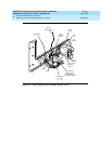
■ In an AC-Powered system, turn off the power in each cabinet
individually. The ON/OFF switch is located at the rear of the carrier
behind the WP-91153 Power Unit.
■ In a DC-Powered system, turn off the power in each cabinet
individually. The ON/OFF switch is located at the rear of the
cabinet, behind the 676B Power Unit.
Procedure for a Single-Carrier Cabinet EPN
This procedure applies to a single-carrier EPN with or without high or critical
reliability, where the cabinet is powered by either an AC or a DC power source.
Power may be removed from the EPN without affecting the PPN.
NOTE:
In a high or critical reliability system, if power is to be removed from an
individual cabinet only, make sure that the affected cabinet does not
contain an Expansion Interface circuit pack that is part of the Active
Expansion Link or an Active Tone-Clock. To determine which Expansion
Interface Link and Tone-Clock are active, issue the status system
command. To determine the synchronization reference, use the display
synchronization command.
1. To remove power from the cabinet:
■ In an AC-Powered system, turn off the power in each cabinet
individually. The ON/OFF switch is located at the rear of the cabinet
behind the WP-91153 Power Unit.
■ In a DC-Powered system, turn off the power in each cabinet
individually. The ON/OFF switch is located at the rear of the cabinet
behind the 676B Power Unit.
Restoring Power
The procedures you need to restore power depend on the system configuration.
Before performing these activities, refer to the following appropriate procedure.
NOTE:
If the AUDIX unit has been powered down, refer to ‘‘Power Up the AUDIX
System’’ on page 5-8.


