DEFINITY Enterprise Communications Server Release 5
Maintenance and Test for R5vs/si
555-230-123
Issue 1
April 1997
Maintenance Object Repair Procedures
Page 10-230CABINET (Cabinet Sensors)
10
2. The following must be done to determine if the front fan or the rear fan has
failed:
a. Test the front fan:
Measure the input impedance between the (+) and (-) input
terminals of the front fan with an ohmmeter. IMPORTANT: Attach
the "common" lead of the ohmmeter to the fan’s (-) input
terminal and the "ohms" or "+" lead of the ohmmeter to the
fan’s (+) input terminal.
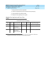
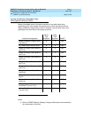
Follow the guidelines in the table below:
b. Test the "paired" rear fan:
From the front of the cabinet, use a voltmeter to measure the DC
voltage across the two female contact pins in the connector
housing of the fan wire harness removed from the inoperative front
fan in Step 1. (This voltage is the same voltage seen across the
input terminals of the paired fan in the rear of the assembly.)
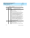
Follow the guidelines in the table below:
3. To replace a fan located at the front of the switch cabinet, remove the fan
assembly cover by pulling the cover outward. To replace a fan located at
the rear of the switch cabinet, use a No. 10 slot screwdriver or 5/16-inch
(8mm) wrench and remove the panel covering the fan assembly.
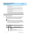
4. Loosen and remove the retaining screw nearest the power plug on the
defective fan.
!
DANGER:
48-volt power is present on the fan plug.
5. Disconnect the power plug from the defective fan.
6. Loosen and remove the other retaining screw on the fan.
Input Impedance Fan Analysis Action Next Step
2.0M < ohms < 20M Good None Go to Step 2B
ohms < 2.0M Short Circuit Replace Go to Step 3
ohms > 20M Open Circuit Replace Go to Step 3
Input
Impedance Fan Analysis Action Next Step
VDC > 25V Good (AHD1 or Front Fan failed)
VDC < 25V Short Circuit Replace Go to Step 3


