DEFINITY Enterprise Communications Server Release 5
Maintenance and Test for R5vs/si
555-230-123
Issue 1
April 1997
Maintenance Object Repair Procedures
Page 10-426DETR-BD
10
DETR-BD
G1, G3iV1.1-286, and those G3iV2-386 systems that use the Mu-law
companding mode use TN748 Tone Detector circuit packs or TN756
combination Tone Detector-Tone-Clock circuit packs. G3iV2-386 systems that
use the A-Law companding mode use TN420B (and higher suffixes) Tone
Detector circuit packs. The companding mode of the DETR-BD circuit pack must
match that administered for the system for proper tone detection. The
companding mode is administered on the System-Parameters Country-Options
form. Refer to
DEFINITY Communications System Generic 3 Implementation
,
555-230-653.
For all DETR-BD circuit pack level errors, refer to XXX-BD (Common Port Board)
Maintenance documentation.
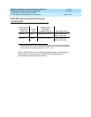
1. Where P is the port network number (1 for PPN, 2 for EPN, and 3 for EPN2); C is the carrier
number (for example, A, B, C, D, or E); SS is the address of the slot in the carrier where the circuit
pack is located (for example, 01, 02, ..., etc.).
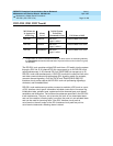
MO Name As It
Appears in
Alarm Log Alarm Level
Initial System
Technician Command
to Run
1
Full Name of MO
DETR-BD MINOR test board PCSS Tone Detector Circuit Pack
DETR-BD WARNING test board PCSS Tone Detector Circuit Pack


