DEFINITY Enterprise Communications Server Release 5
Maintenance and Test for R5vs/si
555-230-123
Issue 1
April 1997
Routine Maintenance Procedures
Page 5-11Replacing Components (Release 5vs or Later)
5
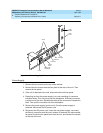
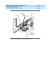
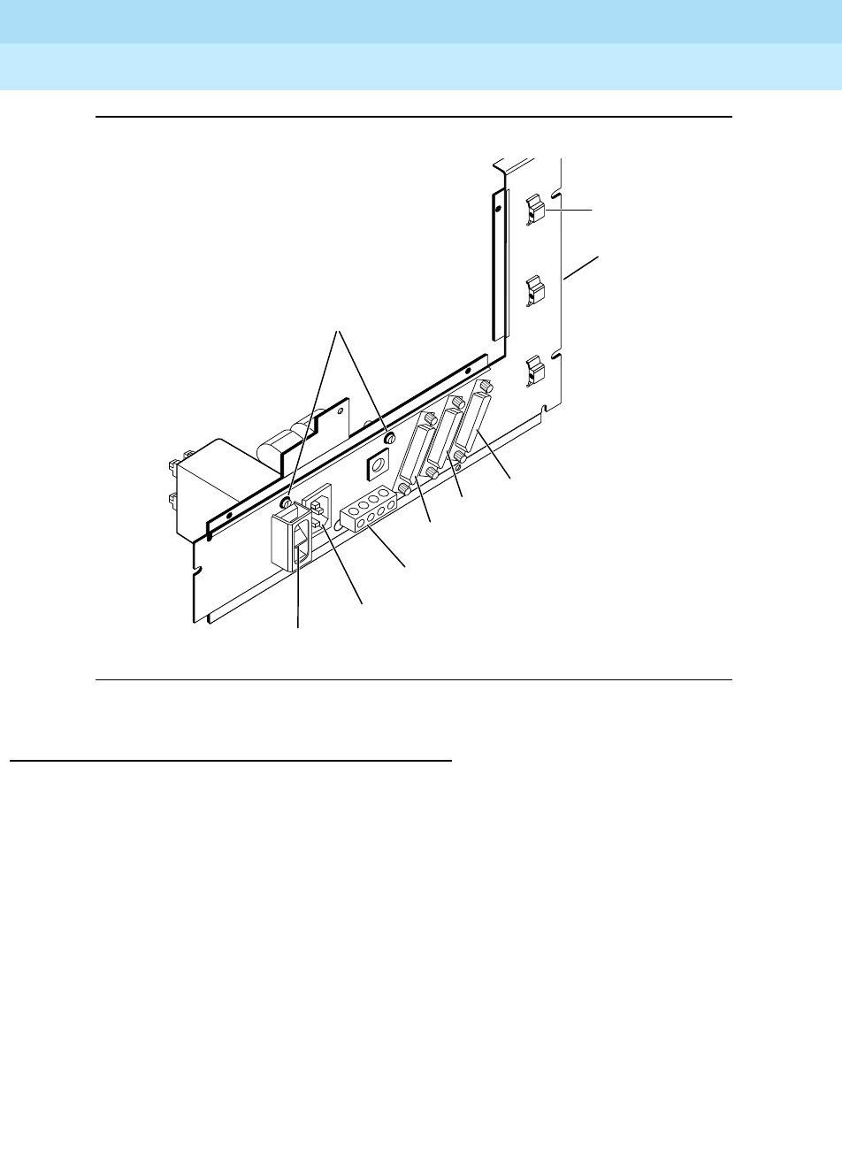
Figure 5-1. Power Supply Sub-Assembly (Outside View)
Power Supply
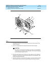
1. Remove the four screws on the top of the cabinet.
2. Remove the four screws from the fan panel at the rear of the unit. Then
remove the fan panel.
3. If the unit is attached to the wall, disconnect the entire fan panel.
4. Extending out from the power supply is a cord consisting of numerous
individual wires. This cord plugs into the backplane. A Burndy connector
is at the end of the cord. Squeeze the sides of the connector to release the
latch. Then pull the connector off of the backplane.
5. Remove the power supply from the unit. Once the power supply is
removed, disconnect the AC power cord.
6. Reconnect the AC power cord, insert the new power supply, reconnect
the Burndy connector and the cord, reinsert (if removed) the reconnected
fan panel, screw the fan panel back onto the unit, and reinsert the screws
on the top of the unit.
Screw
Cable
Retainer
Power
Panel
DCE
Connector
PI
Connector
Ground
Block
Power Cord
Receptacle
Term
Connector
On/Off


