DEFINITY Enterprise Communications Server Release 5
Maintenance and Test for R5vs/si
555-230-123
Issue 1
April 1997
Maintenance Object Repair Procedures
Page 10-681EXP-INTF (Expansion Interface Circuit Pack)
10
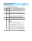
FAIL The test tone was not detected correctly in either direction.
1. Run the test for the Active Tone-Clocks on the Port Networks for
which the Expansion Interface circuit pack under test provides a
link. This will determine if the dial tone is being supplied.
2. Check for disconnected transmit or receive fiber on both ends of
the fiber. Make sure both endpoint circuit packs are inserted and
have no on-board alarms.
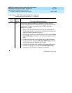
1 or 2 FAIL The test tone was detected correctly in only one direction.
1. Run the test for the Active Tone-Clocks on the Port Networks for
which the defective Expansion Interface circuit pack provides a
link. This determines if the dial tone is being supplied.
2. Check for disconnected transmit or receive fibers on both ends of
the fiber.
3. If Test #238 is failing, refer to procedures for Test #238.
4. If Error Type 2305 has been logged against this Expansion
Interface circuit pack, or the Expansion Interface circuit pack on
the opposite end of its fiber, in the last five minutes, this test may
have failed due to the associated slips. If such errors exist, first
resolve them, and then repeat this test.
5. Execute the test board PCSS long command on both Expansion
Interface circuit packs and follow procedures for Test #242 to
determine if the problem lies with one of the Expansion Interface
circuit packs, the lightwave transceivers, or the fiber itself.
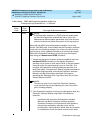
PASS The tone was successfully transmitted in both directions. Both
Expansion Interface circuit packs and their lightwave transceivers
are functioning properly.
0NO
BOARD
No board was detected by the test.
1. Check the error log for wrong board (error 125) or no board (error
131). Resolve either of these issues, if applicable.
2. Check that the board is properly translated and inserted. If so,
check for hyperactivity (error 1538). If hyperactive, use the reset
board PCSS command.
3. Run the test again. If it fails, the ID chip on board may be bad.
Replace the board and retest.
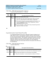
Table 10-194. TEST #241 Expansion Interface 2-Way Transmission Test
— Continued
Error
Code
Test
Result Description/Recommendation
Continued on next page


