DEFINITY Enterprise Communications Server Release 5
Maintenance and Test for R5vs/si
555-230-123
Issue 1
April 1997
Maintenance Object Repair Procedures
Page 10-225CABINET (Cabinet Sensors)
10
current limiter card (982LS), over a wiring harness from the A carrier to the back
of the fan unit, through the AHD1 circuit pack, and then to the fans. The front fans
are wired in parallel with a rear fan. The repair scenarios that follow rely on the
technician’s ability to distinguish between high fan speed and low fan speed. The
only way to distinguish between the fan speeds is by the sound of the fans. When
operating at high speed, the fans make a higher pitched sound than when they
run at low speed. The technician probably knows from prior experience what the
fans sound like at low speed as well as at high speed.
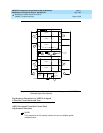
Figure 10-10 shows a multicarrier cabinet system and the location of the
temperature sensors S1 through S4 (there are actually two S3 sensors and two
S4 sensors) as well as the location of the fans, the AHD1 circuit pack, and the
filters. The figure also shows other environment-related components of a
multicarrier cabinet system and can be ignored for this section on Cabinet
Sensors.


