DEFINITY Enterprise Communications Server Release 5
Maintenance and Test for R5vs/si
555-230-123
Issue 1
April 1997
Maintenance Commands and Trouble-Clearing Aids
Page 8-326reset system
8
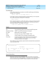
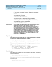
The reset system interchange command does not disrupt in-progress calls.
However, it drops links to local and remote administration terminals and also
drops and re-establishes connections on the Network Control Circuit Pack data
channels. This includes CDR and PMS links. No new calls can be made during
the interchange, but stable calls are not affected.
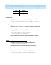
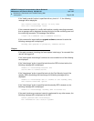
When a system restart occurs with the corresponding vector bit set, a core dump
is written to memory card, only if the memory card is the special core dump
card), the vector is cleared, and the requested restart is performed.
All successful reset system commands will log the user off.
Defaults
None.
Parameters
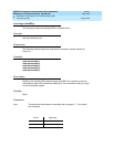
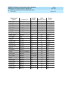
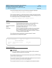
llevel The reset levels are entered numerically with a range of 1 - 5, the levels
are as follows, and the approximate times are listed for each
appropriate level and system configuration:
Level Recovery
SMALL
Flash
MEDIUM
Flash
1 Warm Restart
2Cold-2
3Cold-1
4 Reboot
5 Extended Reboot
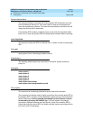
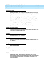
interchange Control of the system passes to the standby SPE as the active SPE
becomes the standby SPE and the standby SPE becomes the active
SPE. The optional "health-override" qualifier can be entered to force an
interchange even if the Fault Severity Level of the standby SPE would
normally cause the maintenance software to abort the interchange.
The Fault Severity Level of an SPE is determined by the alarmed
components in that SPE. Each component is given a severity level, and
the single worst alarm (severity) for a SPE defines Fault Severity Level
for the SPE. The table below lists the maintenance objects, their
alarms, severities and the restart level of the interchange that affect a
SPE’s Fault Severity Level.


