DEFINITY Enterprise Communications Server Release 5
Maintenance and Test for R5vs/si
555-230-123
Issue 1
April 1997
Maintenance Object Repair Procedures
Page 10-1328SYNC (Synchronization)
10
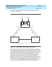
port networks. The
master
port network is defined as the port network whose
Tone-Clock is connected to the Stratum 3 clock.
NOTE:
The Stratum 4 equipment (usually a PBX) should never provide timing to a
Stratum 3 PBX.
NOTE:
The external Stratum 3 clock may be connected to the TN780 Tone-Clock in
any port network. However, it is recommended that it be connected to the
PPN.
Synchronization Troubleshooting
For both Stratum 3 and 4 operation, major and minor alarms indicate that there is
a problem with the system synchronization references. These alarms are
resolved when the alarmed synchronization reference is restored.
The status synchronization and display synchronization commands are used
to determine the current system synchronization reference and the primary and
secondary references that are administered respectively.
Other commands associated with Synchronization Maintenance are disable
synchronization-switch and enable synchronization-switch. These
commands are used to disable the ability of Synchronization Maintenance to
switch between synchronization references and to enable this switching ability,
respectively. The set synchronization command is executed only after
synchronization has been disabled and is used to manually switch to a specific
synchronization reference. This command is useful to diagnose synchronization
problems by forcing a specific reference (DS1 or Tone-Clock) to be the system
synchronization reference to determine if a specific reference is providing a valid
timing signal. For Stratum 3 operation, only a TN780 Tone-Clock circuit pack may
be specified. To switch synchronization to the Stratum 3 clock, use the enable
synchronization-switch command after verifying that the Stratum 3 clock is
wired correctly.
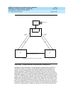
The system synchronization planner must avoid creating a
timing loop
when
administering the primary and secondary synchronization references in a
system. A timing loop exists whenever a system receives timing from another
system whose timing reference is directly or indirectly derived from itself. Timing
loops can lead to loss of digital data between systems that are exchanging data
with any system within the loop. An invalid timing signal is also generated by any
system within the loop, thus propagating the invalid timing signal to any
system(s) using a system within the loop as a synchronization reference. Figure
10-89 shows a timing loop and a correct distribution of timing between the
systems.


