DEFINITY Enterprise Communications Server Release 5
Maintenance and Test for R5vs/si
555-230-123
Issue 1
April 1997
Reliability Systems: A Maintenance Aid
Page 6-23Repair Procedures for High and Critical Reliability
6
NOTE:
Do not remove power before proceeding with step 2. All PPN Control
Carriers used in High or Critical Reliability Systems (A slot for the
Duplication Interface circuit pack identifies these carriers.) have
staggered pins to support the hot plug-in of circuit packs.
2. Unseat the Standby SPE Processor circuit pack. (It is not necessary to
entirely remove the Standby SPE Processor circuit pack from its slot.)
3. If the circuit pack to be replaced is the TN772 Duplication Interface in the
A carrier, continue with this step. Otherwise, proceed to Step 4.
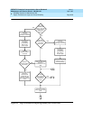
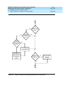
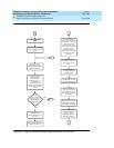
Issue the status system command from the terminal, and check the
status of the Tone-Clock in the 1B carrier:
a. If the SERVICE STATE field indicates that the 1B carrier Tone-Clock
is “in” (that is, in service) and the SYSTEM CLOCK and SYSTEM
TONES fields indicate that it is “active,” proceed to Step 4.
b. If the SERVICE STATE field indicates that the 1B carrier Tone-Clock
is “in” (that is, in service) but the SYSTEM CLOCK and SYSTEM
TONES fields indicate that it is “standby,” then check the Error Log
for an active Error Type 3329 against the 1B TONE-BD by issuing
the display error command. If this error exists, proceed to Step 4.
NOTE:
Error Type 3329 implies that the Tone-Clock circuit pack
probably cannot provide system clocks and an attempt to set
the system clocks to this circuit pack would result in a reset
system 2 of the system. When the 1A Duplication Interface
circuit pack is replaced, however, the system experiences a
loss of clock, and a reset system 2 occurs.
If an active Error Type 3329 is not logged against the 1B TONE-BD,
issue the set tone-clock 1B command from the G3MT terminal to
make the 1B carrier Tone-Clock active. Verify that the switch occurs
by issuing the status system command and checking that the
SERVICE STATE, SYSTEM CLOCK and SYSTEM TONES fields are
now “in” and “active.” Proceed to Step 4.
NOTE:
If the 1B Tone-Clock circuit pack is defective the switch may
have failed and a reset system 2 may have occurred. In this
case, proceed to Step 4. However, the system experiences a
loss of clock and another reset system 2 when the 1A
Duplication Interface circuit pack is replaced.
c. If the SERVICE STATE field indicates that the 1B carrier Tone-Clock
is “out” (that is, out-of-service), refer to the TONE-BD (Tone-Clock
circuit pack), TONE-PT (Tone Generator), and TDM-CLK (TDM Bus
Clock) Maintenance documentation in Chapter 10, ‘‘
Maintenance


