DEFINITY Enterprise Communications Server Release 5
Maintenance and Test for R5vs/si
555-230-123
Issue 1
April 1997
Routine Maintenance Procedures
Page 5-53System Features
5
.
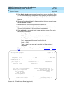
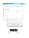
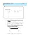
Screen 5-5. Trunk Group Form — Simplex Mode (Page 2 of 5)
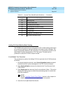
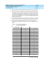
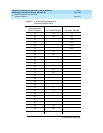
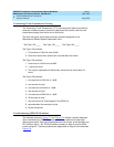
4. Locate the Tie Trunk port terminal connections at the cross-connect field.
See Table 5-4
.
5. At the cross-connect field, disconnect outside trunk facilities from the
Analog Tie Trunk ports and mark the disconnected wires for later when the
Tie Trunk ports are placed back into normal operation. The D Impact Tool
(AT-8762) is required to perform this step.
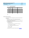
6. Use jumper wires (DT 24M-Y/BL/R/G) and the D Impact Tool to connect
wiring between the two ports assigned in Step 4 at the cross-connect field.
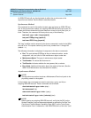
For example, if the two ports on the Analog Tie Trunk circuit pack are ports
1 and 2, connect the wirings as shown below:
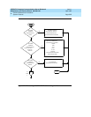
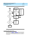
7. Repeat Steps 13 through 16 of the E & M Mode Test Procedure.
Page 2 of 5
TRUNK GROUP
GROUP MEMBER ASSIGNMENTS
Port Name Mode Type Answer Delay
1: B1901 simplex type 5
2: B1902 simplex type 5
3:
4:
5:
6:
7:
8:
9:
10:
11:
12:
13:
14:
15:
simplex simplex
5 type 5 type
R2
R11
T2
T11
R12
R1
T12
T1
2 Port 1 Port


