DEFINITY Enterprise Communications Server Release 5
Maintenance and Test for R5vs/si
555-230-123
Issue 1
April 1997
Reliability Systems: A Maintenance Aid
Page 6-5Duplicated Hardware
6
Tone-Clock circuit packs which of the two is currently the active one. These leads
are known as the Tone-Clock Select leads. System software can request that the
SPE Select lead and/or the Tone-Clock Select leads be changed. Duplication
Interface A controls and monitors in the PPN of a High or Critical Reliability
system the same set of environmental leads that the EPN TN775 or TN775B
Maintenance circuit pack controls and monitors in an EPN.
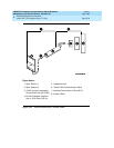
The Duplication Interface circuit packs communicate with one another over the
Inter-Carrier Cable (ICC). In a multicarrier cabinet, the ICC physically consists of
two 25-pin connector cables known as ICC-A and ICC-B. In a single-carrier
cabinet, the ICC physically consists of three 25-pin connector cables known as
ICC-A, ICC-B, and ICC-C. The ICC connects the Duplication Interface circuit
packs via pin fields on the backplane. The pin fields where ICC-A and ICC-B
(and ICC-C in a single-carrier cabinet) are connected are labeled on the
backplane near the pin fields for the Duplication Interface circuit packs. The ICC
carries leads related to maintaining a High or Critical Reliability system.
Furthermore, without the ICC properly attached, the system cannot function as
either a High or Critical Reliability system or as a Standard system.
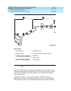
The Duplication Interface circuit packs support serial links that provide for G3 MT
connection, memory shadowing from Active SPE Memory to Standby SPE
Memory, and communication between software on the Active SPE and the
Standby SPE. Four serial links are supported:
1. The serial link from Duplication Interface A to the G3 MT.
2. The serial link from Duplication Interface A to the Maintenance/Tape
Processor in carrier A.
3. The serial link from Duplication Interface A to the Maintenance/Tape
Processor in carrier B.
4. The serial link from Duplication Interface A to Duplication Interface B.
NOTE:
The Duplication Interface B circuit pack does not communicate directly with
either Maintenance/Tape Processor or with the G3MT.
Duplication Interface A supports the serial channel to the G3MT that is
connected to the Duplication Interface A circuit pack by a connector on the back
of carrier A labeled “DOT” (Duplication Option Terminal). If the Duplication
Interface A circuit pack becomes defective, and the B carrier becomes the
Active SPE, the terminal can be connected to the Maintenance/Tape Processor
in carrier B by connecting the terminal to the connector labeled "TERM" on the
back of carrier B. If the Duplication Interface A circuit pack becomes defective
and carrier A becomes the Active SPE, the terminal can be connected to the
Maintenance/Tape Processor in carrier A by connecting the terminal to the
connector labeled "TERM" on the back of carrier A.
Communication between software on the Active SPE and the Standby SPE is
conducted via a message flow between the two Processors. The flow of
messages from the Processor in carrier A to the Processor in carrier B is as


