DEFINITY Enterprise Communications Server Release 5
Maintenance and Test for R5vs/si
555-230-123
Issue 1
April 1997
Maintenance Object Repair Procedures
Page 10-850MAINT (EPN Maintenance Circuit Pack)
10
MAINT (EPN Maintenance Circuit
Pack)
The EPN Maintenance circuit pack monitors and supports environmental
maintenance for the EPNs. The EPN Maintenance circuit pack provides the
switch software, a mechanism to enable and disable Emergency Transfer in the
EPN (assuming the Emergency Transfer Switch is in the AUTO position). The
EPN Maintenance circuit pack invokes Emergency Transfer when the EPN loses
contact with the PPN or the EPN Maintenance circuit pack loses contact with all
Expansion Interface circuit packs. When AC power fails in the EPN cabinet, no
power holdover is available. If an Expansion Interface circuit pack goes insane
and is reset six times within 15 minutes, the EPN Maintenance circuit pack holds
the Expansion Links reset (which prevents the Expansion Interface circuit pack
from running).
The EPN Maintenance circuit pack provides system level alarm LEDs which
indicate the absence or presence of Major, Minor, and Warning alarms within the
entire system (PPN and EPN).
The EPN Maintenance circuit pack supports a G3MT terminal which runs at 9600
baud. However, the system software throttles the rate of data flow to the EPN
Maintenance circuit pack for display on the terminal to about 1200 baud. All
system commands can be executed via the EPN terminal. However, due to the
slow speed at which the software runs the terminal, it is recommended that the
EPN terminal’s primary use be for system maintenance rather than system
administration.
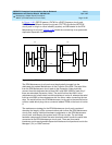
The PPN communicates with the EPN Maintenance circuit pack using the
following path (messages from the EPN Maintenance circuit pack to the PPN take
exactly the reverse path). From the PPN, TN773 Processor circuit pack, EPN
Maintenance circuit pack messages are passed to the Switch Control on the
Network Control circuit pack over the Memory Bus (MBUS) and then over the
TDM Bus to the Active PPN Expansion Interface circuit pack. The Active PPN
Expansion Interface circuit pack passes the message across the fiber to the
Active EPN Expansion Interface circuit pack. The Active EPN Expansion
Interface circuit pack then passes the message over a serial link to the EPN
Maintenance circuit pack. Figure 10-62
illustrates this path.
MO Name (in
Alarm Log)
Alarm
Level Initial Command to Run Full Name of MO
MAINT MINOR test maintenance sh EPN Maintenance Circuit Pack
MAINT MAJOR test maintenance l EPN Maintenance Circuit Pack


