DEFINITY Enterprise Communications Server Release 5
Maintenance and Test for R5vs/si
555-230-123
Issue 1
April 1997
Maintenance Commands and Trouble-Clearing Aids
Page 8-257monitor system
8
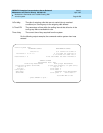
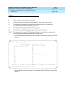
For the following output example, the command monitor system view2 was
entered.
Output
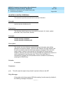
The following output fields are for the "monitor system conn" command.
Time Slot
Status
There are 4 numbers associated with the time slot status for each
specified pnn; for each of the two buses (0 and 1) there is a
maintenance and a normal state. The first row is the pnn, the second
specifies the bus while the third specifies the bus’s state while the last
column represents the number of idle counts. These fields represent
real-time status data.
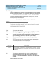
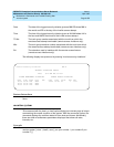
Bus Status For the bus status fields, there are two numbers associated with each
of the two buses for each pnn. Shown are the pnn number; the bus
associated with it, i.e., 0 or 1; and the state of the bus, i.e., "avail" or
"unavail". These fields represent real-time status data.
Callrate The callrate field represents the call rate being experienced currently
on the switch. This is a counter which is bumped each time a call
attempt is made. This field represents real-time status data.
Interval This field is related to the above field in that it represents the interval
being applied with which the call rate is applicable. It is normally set to
a 36 second time period. This field represents a constant status data.
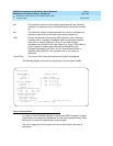
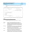
monitor system view2
ATTENDANT STATUS MAINTENANCE STATUS
Console no. # of alarms for trunks: 4
Activated: 1 2 3 4 5 6 # of alarms for stations: 2
# of alarms for other res: 1
Deactivated: 7 8 First OSS number has been informed? n
TRAFFIC STATUS Measurement Hour: 1800
Trunk Group Measurement
(4 grps with highest %time ATB)
Grp no: 78
Grp dir:
Calls qued: 1
%Out blkg:
%Time ATB:
Attendant Group Measurement
Calls qued: 1 Calls aban: 0
16:08 WED MAR 6 1996
- press CANCEL to quit -


