DEFINITY Enterprise Communications Server Release 5
Maintenance and Test for R5vs/si
555-230-123
Issue 1
April 1997
Maintenance Object Repair Procedures
Page 10-1313SW-CTL (Switch Control)
10
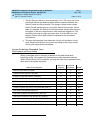
c. If the Aux Data is less than 100, the test may have been interrupted by
LMM operations. Wait 1 minute, then test again. Retry the test a maximum
of three times. If the Aux Data is more than 100 or fails two out of three
times with Aux Data less than 100, the Netcon circuit pack needs to be
replaced.
d. A 769 error occurs when the Switch Control reports a loss of timing signals
to the processor. When this error is present, the Switch Control is usually
not alarmed since any Switch Control test failures are really the result of
faulty signals from the PPN cabinet Tone-Clock circuit pack. See
TDM-CLK (TDM Bus Clock) Maintenance documentation for the
procedures needed to diagnose Tone-Clock circuit pack troubles.
e. This error indicates a loss of handshake between SW-CTL and the system
software. Look for and resolve all other SW-CTL errors. In the rare case
where no other errors are logged, but Error Type 1281 is occurring at a
high rate (more than 10 in the previous hour), escalate the problem.
For G3s, a loss of handshake between Switch Control in Network Control
circuit pack (TN777B) and Processor circuit pack (TN786B or TN790) can
be caused by the following components: Network Control circuit pack
(TN777B), Processor circuit pack (TN786), Processor Interface circuit
pack (TN765), Packet Control circuit pack (TN778), and M-BUS.
Follow these repair steps:
1.Look for and resolve all other SW-CTL errors.
2.Look for and resolve all other PI-SCI, PI-BD, and PKT-CTRL errors.
3.If the error indicates a failure in the Network Control circuit pack,
Chapter 6, ‘‘
Reliability Systems: A Maintenance Aid’’ for instructions
to replace the Network Control circuit pack. Boot the system up
after the Network Control circuit pack has been inserted
successfully into the control carrier.
4.If the error of loss of handshake persists after the replacement of the
Network Control circuit pack, then refer to Chapter 6, ‘‘
Reliability
Systems: A Maintenance Aid’’ for instructions to replace the
Processor circuit pack.
Refer to the "Software Upgrade" section in Chapter 5, ‘‘
Routine
Maintenance Procedures’’, to load the system software from the
Memory Card (J58890TG-1 List 3) with the correct software release
into the Processor circuit pack. Boot the system up after the system
software is successfully loaded into the Processor circuit pack.
5.If the error of loss of handshake persists after the replacement of the
Processor circuit pack, consider the replacement of the control
carrier. It’s possible that the M-bus on the backplane of the control
carrier may be defective.
Recommended Repair Kits: Network Control circuit pack
(TN777B), Processor circuit pack (TN786B or TN790), and Memory
Card (J58890TG-1 List 3) with correct software release.


