DEFINITY Enterprise Communications Server Release 5
Maintenance and Test for R5vs/si
555-230-123
Issue 1
April 1997
Maintenance Object Repair Procedures
Page 10-1132POWER (Battery & Battery Charger) for AC-Powered Systems
10
8
(cont’d.)
FAIL
(cont’d.)
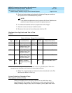
3. Procedures for a Global MCC (J58890CH):
a. Look to see if any “red” LEDs are “on” on any of
the rectifier modules or the BIU (Battery Interface
Unit) located in the Power Distribution Unit
(J58890CH).
b. If the BTW (Battery Temp Warning) LED on the
BIU is “on” check the batteries for a over temp
condition
(a)
if temp is normal
(a)
replace the BIU, If
the test still fails replace the battery in a small
battery system. For a large battery system
escalate the problem.
c. If the BIF (Battery Interface Unit) LED is “on”
replace the battery interface unit.
d. If the BNA (Battery Not Available) LED is “on”
check the battery connections including
connector J20.
e. If you have an alarm and all LEDs are ok (PWR
OK and BOK) on the rectifier modules, and the
BIU (Battery Interface Unit), make sure the BIU
and the RM0850 rectifiers are seated properly
(plugged in). If the BOK LED on the BIU is ok use
the following information to check the number of
rectifiers serving this cabinet:
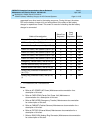
Number of carriers Number of rectifiers
per cabinet per cabinet
----------------------------|---------------------------------
1 2
2 3
3 3
4 4
5 4
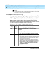
If the number of rectifiers is correct replace the
maintenance circuit pack in the EPN or PPN.
4. If the test still fails, then follow normal escalation
procedures.
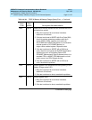
Table 10-332. TEST #5 Battery & Battery Charger Query Test — Continued
Error
Code
Test
Result Description/ Recommendation
Continued on next page


