DEFINITY Enterprise Communications Server Release 5
Maintenance and Test for R5vs/si
555-230-123
Issue 1
April 1997
Packet Bus Fault Isolation and Correction
Page 9-28Packet Bus Fault Correction
9
If the Packet Bus problem is present when the circuit pack is inserted, but is
resolved when the circuit pack is removed, either the circuit pack or the
backplane pins in that slot caused the problem. If the backplane pins are intact,
replace the circuit pack.
NOTE:
In a multiple failure situation, the circuit pack could be one cause of the
Packet Bus problem. However, there could also be other failures that are
causing Packet Bus faults.
In Procedure 2, an option of working either with one circuit pack at a time or with
multiple circuit packs simultaneously is available. In view of this, determine the
level of service interruption to be allowed during this procedure. If causing a
disruption to all users in the port network is deemed permissible, large groups of
circuit packs should be worked with. This option allows faster job completion.
However, if large service disruptions are to be avoided, work with one circuit
pack at a time
. This option is slower, but it disrupts only the users of a single
circuit pack.
!
CAUTION:
If the TN771 Standalone mode does NOT indicate Packet Bus faults,
perform Procedure 2 for ONLY the port (purple) slot Packet circuit packs
listed in Table 9-1
. Also, problems with the backplane pins need not be
checked for. Determining if the problem is resolved by removing circuit
packs is sufficient.
Steps for Procedure 2:
1. Remove one or several circuit packs as appropriate, according to the
considerations presented in the previous paragraphs. Any circuit pack(s)
(whether Packet or non-Packet) that have been recently inserted should
be checked first. It is likely that such a circuit pack caused a new problem.
Keep in mind that Packet circuit packs should be checked before
non-Packet circuit packs.
If the decision is made to remove multiple circuit packs, consider working
with an entire carrier at a time to ensure a good granularity.
2. Determine if the Packet Bus fault is still present.
3. If the Packet Bus fault is still present:
■ Determine if the backplane pins in the removed circuit pack’s slot
are bent. Use the output from the Maintenance/Test standalone
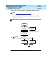
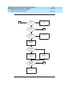
mode and Figure 9-3
and Figure 9-4.
■ If the backplane pins are bent, power down the carrier (refer to the
"Removing Power" section in Chapter 5, ‘‘
Routine Maintenance
Procedures’’, straighten or replace the pins, reinsert the circuit
pack, restore power (refer to the ‘‘
Restoring Power’’ section in
Chapter 5
, and repeat Procedure 2, beginning with Step 2, for the
same circuit pack.


